Do I feel safe?
Am I doing everything right?
You will know for sure in a few minutes.
Safety tests are mandatory and are part of every final inspection of your electrical product.
Learn the most important facts about the insulation resistance test.
We explain the WHY?, WHERE?, HOW? and also the WHEN NOT!
And if you would like to learn more, you can download even more detailed information at the end of this page free of charge!
WHY?
Safe insulation is the central protective measure to ensure electrical safety. It ensures that the user does not touch live conductors and that no short circuit can occur between the conductors or to the housing of the equipment. Because if it did occur, a life-threatening current could flow through the user if he or she touched the housing. Obviously, the protective earth conductor should ensure that this does not happen. But in the worst case it could also be defective. And it would also only be an evasion of the effect, not of the cause.
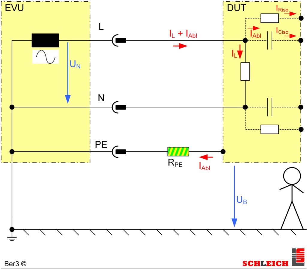
In order to guarantee all this, the insulation must work perfectly! And you must prove and document this by carrying out an insulation resistance test before the electrical product is delivered.
The insulation resistance test is a routine test. This means that every piece, i.e. every single electrical product that you put on the market, necessarily requires an insulation resistance test.
WHERE?
It is somewhat more complicated than in the case of the protective earth conductor, for example. Basically, there must be good insulation between current-carrying conductors or between these and housing parts. Typically, this is done by insulating the electrical conductors against dangerous contact, i.e. covering them with an insulating material. But this protective sheath must be removed at the latest when the electrical conductor is connected to other electrical components. At these points, the insulation is guaranteed over a safe distance. It is then a matter of safety distances through clearance and creepage distances.
In addition, current-carrying conductors can also be insulated from each other, e.g. by means of casting compounds, insulating foils or solids.
When is which type of insulation used?
This always has to do with the design of the electrical product, the type of specification such as high temperature or mechanical load etc.
Now it is certainly understandable that insulations in a luminaire, an electric iron, an electric motor or a high-voltage insulator in a power station have very different requirements and designs.
From this diversity, quite complex electrotechnical insulation structures result from case to case.
HOW?
Since the insulation has “something to do with the voltage”, the test is carried out with a defined test voltage level. This can be ramped up or applied directly to the device under test at its full magnitude.
The aim is to measure the current and then calculate the insulation resistance, as this is the evaluation criterion for the insulation. It must be equal to or greater than a specified minimum resistance.
The lower limit of the insulation resistance can be defined differently from product to product and in different regions/continents. Therefore, you must always take the test parameters from the standard applicable to the product and region.
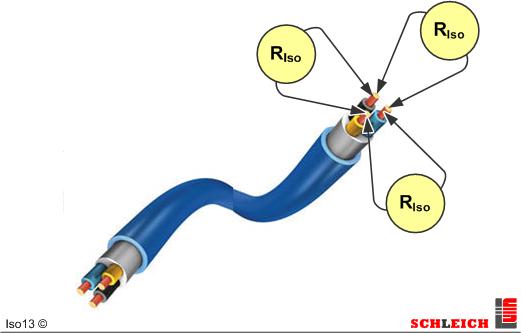
Often the insulation resistance is measured one after the other between all the conductors involved in the electrical product. These can be combined groups of conductors or individual conductors and of course the housing or housing parts. It quickly becomes clear that the test can and must be carried out at a wide variety of locations, depending on the complexity of the electrical product.
This could be done by scanning the test points with a test probe – an approach that can quickly turn out to be lengthy and costly.
For 25 years, complex tests have therefore always been carried out automatically at any test points via the SCHLEICH-typical matrix, which is fully programmable:
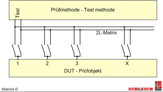
SCHLEICH switching matrixes switch flexibly in 2- and 4-wire technology. Especially 4-wire technology is of great importance in automated systems and plants. It guarantees a safe contact control of the test voltage and thus process stability.
| Test paramters | typical norm values | SCHLEICH | from standard to customized |
| minimum permissible insulation resistance | 1, 2, 100 MΩ | from 100 kΩ to 10 TΩ |
| minimum required test voltage | 500 V DC | from 30 to 50,000 V DC |
| max. safety test current by SCHLEICH | 3 – 12 mA | from 3 to 100 mA |
| minimum test duration | 1 s | from 0,1 s to 1 month |
| start-up ramp | off; 1 s – 1 min | off; from 0,5 s to1 month |
| down ramp | off; 1 s – 1 min | off; from0,5 s to1 month |
| step voltage test | off; in 5 steps | off; in any number of steps |
| DAR / PI | off; 3 – 5 | off; 1 – 10 |
With this range of requirements, it is of course ideal to use a test device that covers as many of the world’s standards as possible.
That is SCHLEICH’s strength.
The TEST DURATION?
An insulation always consists of an insulation resistance and a capacitor? Why a capacitor? Was that even built in? …
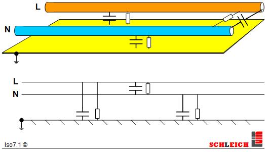
The insulation measurement always takes place between electrical conductors and/or housing parts. In an abstract way, these two components form two metal surfaces that have a certain distance between them. Between them is the insulation. And this structure corresponds to a capacitor. Consequently, the whole insulation structure also behaves similar to a capacitor.
After applying the test voltage, the capacitor will of course charge first. Only when the capacitor is charged, all that remains is the current through the insulation resistance.
It becomes clear that therefore an insulation resistance measurement cannot be carried out within tenths of a second in many cases due to physical limitations. The tester could – but the device under test “is not yet ready”.
| capacitive part of the insulation | typical test times | Examples |
| low | 1 s | Household products, lamps, assemblies, power tools, machines and equipment … |
| medium | 10 – 30 s | small to medium-sized electric motors, frequency converters … |
| high | 60 – 600 s | large electric motors/generators, cable reels/cables, several hundred meters long |
Complex structures such as electric motors, windings in general and long cables/ground cables still show polarization effects. To go into this phenomenon is beyond the scope of this article – but this can be read in the free download.
WHEN NOT?
The insulation resistance test is usually always required. Unless, alternatively, a high voltage test is required.
The high voltage test is even more intensive and detects insulation weaknesses very reliably. However, it also has a decisive disadvantage, because the precise measurement of the insulation resistance in MΩ or GΩ is not possible with high voltage AC. The NOGO evaluation is therefore based on a too high leakage current and not on a too low insulation resistance!
The use of both test methods is also frequently found in standards.
The insulation resistance test with 500 V DC for very precise insulation resistance determination and the high voltage test with AC and typically 1500 V or 1800 V test voltage with 100 mA short-circuit current and 500 VA power.
All set? Want more details?
Our mission – know-how, know-how, know-how… Those who understand the test methods with technical and normative certainty will get the most out of their test device.
– Dipl. Ing. Martin Lahrmann
Yes – tell me more. I want maximum security for our customers, our company and myself.
Send me more detailed information from the SCHLEICH test method handbook.

HandHeld
PE-resistance and insulation resistance tester- protective conductor resistance test up to 10 A AC
- insulation resistance test up to 1,000 V
- mobile – lightweight – indoor/outdoor
- transport case – carrying strap
- PC software
- attractive acquisition costs …
- hospital service
- rotor blade lightning protection test on wind turbines …

GLP1-g
PE conductor, insulation, high voltage and function testing deviceThe smallest safety tester in the world!
- PE/GB-resistance testers
- insulation resistance testers – IR
- high voltage testers AC/DC
- safety & function testers
- 50+ device configurations – combining up to 9 test methods in one device
- PLe, SIL3, Kat4 safety circuit (depending on device variant and degree of risk)
- table-top unit or 19″ rack mounting
- ½ 19″ or 19″ format

GLP2-BASIC
Protective conductor, insulation, high voltage, leakage current and function tester- insulation Resistance testers – IR
- high voltage testers AC/DC
- “All in one” testers
- safety & function testers
- app. 40 device variants – combined from up to 21 test methods
- PLe, SIL3, Kat4 safety circuit (depending on device variant and degree of risk)
- network
- protocol & label printing
- scanner …
- Technology Package for even more ergonomics
- table-top unit or 19″ rack mounting

GLP2-MODULAR
Combination tester with up to 25 test methods- “All in one”
- safety testers
- safety & function testers
- modular combination of more than 25 test methods possible
- up to 250 test connections
- large switch matrix modules for all kind test methods
- PLe, SIL3, Kat4 Safety circuit (depending on device variant and degree of risk)
- network
- protocol & label printing
- scanner …
- Technology Package for even more ergonomics

GLP3
Unlimited class leading test technology.The TOP-Class of testing and measuring technology for safety and functional testing.
- “All in one”
- safety & function testers
- for complex projects
- for complex automation
- for the highest demands
- modular combination of more than 30 test methods
- up to 350 test connections
- large switch matrix modules for all kind test methods
- PLe, SIL3, Kat4 safety circuit
- Windows 10®
- network
- protocol & label printing
- industry 4.0
- interfaces to MES, ERP, SPS …

MotorAnalyzer2 R2
The expert level tester for your motor serviceCheck your motor’s health!
- asynchronous, synchronous and direct current machines, brakes, transformers, coils …
- repair, service, maintenance, servicing
- ALL-IN-ONE – 15 test methods in one device
- surge voltage test up to 3 kV !
- high voltage DC and insulation up to 6 kV
- resistance, inductance, impedance, capacitance, RIC test
- troubleshooting and fault location
- adjusting the neutral zone on DC motors
- light and portable
- battery or mains operation
- PC software for printing and saving

MTC2
Surge tester with 6, 12, 15, 25, 30, 40 or 50 kVThe state of the art winding tester.
- surge test plus standard-compliant partial discharge measurement
- resistance
- insulation resistance
- high voltage DC plus polarization index / DAR
- high voltage AC
ideal for service, production, automation, quality control, laboratory, R&D …

MTC3
Winding tester fully automatic for automation, laboratory ...Reliable winding testing for production, research and quality.
▪ standard motors
▪ special motors
▪ automotive drives
▪ transformers
▪ coils …
▪ ALL-IN-1 with over 20 test methods
▪ in-line partial discharge testing
▪ interfaces for automation such as PROFINET, EtherCAT, TCP/IP …
▪ interfaces to ERP, MES and CAQ systems …