Do I feel safe?
Am I doing everything right?
You will know for sure in a few minutes.
Safety tests are mandatory and are part of every final inspection of your electrical product.
Learn the most important facts about the leakage current test.
We explain the WHY?, WHERE? and HOW?
And if you would like to learn more, you can download even more detailed information at the end of this page free of charge!
The INSULATION?
As is the case with the insulation resistance and high voltage test, the leakage current test is all about the quality and safety of the insulation.
The leakage current test takes place during the actual use of the electrical product. For this purpose, the electrical device is connected to the operating voltage and tested to see whether too high a leakage current flows through the insulation to the housing. It is therefore a combination of a safety and functional test.
WHY?
Safe insulation is the central protective measure to ensure electrical safety. It ensures that the user does not touch live conductors and that no short circuit can occur between the conductors or to the housing of the equipment. Because if it did occur, a life-threatening current could flow through the user if he or she touched the housing. Obviously, the protective earth conductor should ensure that this does not happen. But in the worst case it could also be defective. And it would also only be an evasion of the effect, not of the cause.
In order to guarantee all this, the insulation must work perfectly! And this must be proven and documented by you with a leakage current test before the electrical product is delivered.
This test is not mandatory for all electrical products. However, it may well be required for the certification of the electrical product in the type test. If it is required during manufacture, it is a routine test. This means that every piece, i.e. every single electrical product you put on the market, necessarily requires a leakage current test .
HOW?
Since the insulation has “something to do with the voltage”, the test is carried out with increased nominal voltage. The increase is typically + 6%, + 10% or + 15%. The reason: since the mains voltage could be increased by up to + 10% at the end customer’s premises, this should be simulated accordingly during the test. The electrical product is thus in an operating state with overvoltage.
This type of procedure has the advantage that during the test, as many components of the electrical product as possible are temporarily or permanently live.
The test is often referred to as the “warm leakage current test“. Logically, there is also the “cold leakage current test“. Consequently, the electrical product is not operated in this test. The test intensity is lower here.
The aim is to measure the current through the insulation in a wide range of fault conditions. This is because it is the evaluation criterion for the insulation. It must never be greater than a specified maximum current during the entire test period.
The upper limit of the leakage current can be defined differently from product to product and in different regions/continents. Therefore, you must take the test parameters from the standard applicable to the product and region.
The current measurement is not only a simple current measurement with a multimeter!
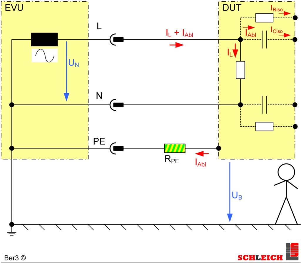
No, the user is simulated by various RC networks (resistor-capacitor networks). These are defined in the standards for different, possible error cases.
The test is carried out under various fault conditions automatically simulated by the tester.
The leakage current in the protective earth conductor of the electrical device is measured.

If there are housing parts on the electrical product that are not connected to the protective earth conductor, the test is performed using a test probe.

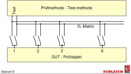
For 25 years, complex tests have therefore always been carried out automatically at any test points via the SCHLEICH-typical matrix, which is fully programmable:
| Test paramters | typical norm values | SCHLEICH | from standard to customized |
| test voltage | 1.05 – 1.1 x Unominal | 1.0 – 1.15 x nominal voltage |
| max. permissible test current | 1 – 30 mA | 1 µA – 500 mA |
| minimum test duration | 1 s | from 0.1 s to 24 h |
| measurement circuits EN60990 | 3 | 1. measurement circuits: unweighted touch current 2. measurement circuits: touch current evaluated for perception and reaction 3. measurement circuits: touch current evaluated for release |
| measurement circuits EN60601 | 1 | 1. measurement circuits: EN60601 |
| measurement circuits UL | 1 | 1. measurement circuits: UL1026 + UL1283 |
| measurement frequency | 500 Hz, 1 MHz | up to 500 Hz / 1MHz |
With this range of requirements, it is of course ideal to use a test device that covers as many of the world’s standards as possible.
That is SCHLEICH’s strength.
LEAKAGE CURRENT up to 1 MHz ?
More and more modern electrical products have integrated electronic components. Very often switching power supplies are used for internal power supply. These can produce pulse-like leakage currents with very high frequency parts of up to 1 MHz. In order to be able to test these, the leakage current measurement technology must also be dimensioned to 1 MHz.
The effort involved is not inconsiderable.
SCHLEICH offers the 1 MHz leakage current test including factory calibration or DAkkS calibration! The harmonic response of the measuring circuit is also documented.
All set? Want more details?
Our mission – know-how, know-how, know-how… Those who understand the test methods with technical and normative certainty will get the most out of their test device.
– Dipl. Ing. Martin Lahrmann
Yes – tell me more. I want maximum security for our customers, our company and myself.
Send me more detailed information from the SCHLEICH test method handbook.

GLP2-BASIC
Protective conductor, insulation, high voltage, leakage current and function tester- insulation Resistance testers – IR
- high voltage testers AC/DC
- “All in one” testers
- safety & function testers
- app. 40 device variants – combined from up to 21 test methods
- PLe, SIL3, Kat4 safety circuit (depending on device variant and degree of risk)
- network
- protocol & label printing
- scanner …
- Technology Package for even more ergonomics
- table-top unit or 19″ rack mounting

GLP2-MODULAR
Combination tester with up to 25 test methods- “All in one”
- safety testers
- safety & function testers
- modular combination of more than 25 test methods possible
- up to 250 test connections
- large switch matrix modules for all kind test methods
- PLe, SIL3, Kat4 Safety circuit (depending on device variant and degree of risk)
- network
- protocol & label printing
- scanner …
- Technology Package for even more ergonomics

GLP3
Unlimited class leading test technology.The TOP-Class of testing and measuring technology for safety and functional testing.
- “All in one”
- safety & function testers
- for complex projects
- for complex automation
- for the highest demands
- modular combination of more than 30 test methods
- up to 350 test connections
- large switch matrix modules for all kind test methods
- PLe, SIL3, Kat4 safety circuit
- Windows 10®
- network
- protocol & label printing
- industry 4.0
- interfaces to MES, ERP, SPS …