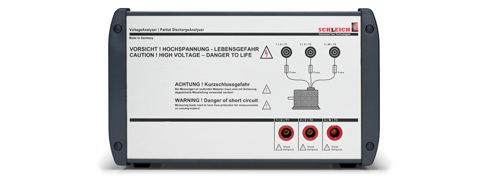
VoltageAnalyzer
Intelligent probe up to 6 kV
Precision measurement of the surge test directly at the winding.
- consideration of the influence of the measuring leads
- ideal for fast surge voltage rise time
- super fast sampling rate
- high measuring resolution
- plus simultaneous PD measurement with passive or active antenna
- integrated switchover between the test leads
Product consultant
Key-Facts
High-precise voltage determination at test objects
- Active test probe with integrated switchover between three phases
- Insulated voltage measurement
- Exact surge voltage measurement at windings
- Elimination of voltage influences on the measuring lead
- Precise measurement of PD-voltages – PDIV, RPDIV, PDEV, RPDEV
- Perfect for standard-compliant measurements according to DIN EN 60034-18-41:2021
- Including determination of pulse rise times
- Determination of voltage peaks caused by frequency converters
Description
Measuring accuracy meets perfection.
The VoltageAnalyzer serves to measure all kinds of high-voltages. The frequency range covers DC voltages up to very high pulse frequencies in the MHz-range.
This it is perfectly suited for high voltage, surge voltage and partial discharge measurements.
The active test probe measures voltages and voltage peaks exactly there, where they appear. This may be e.g. in the motor´s terminal board.
These voltage peaks may be caused by a frequency converter or by harmonics caused by the lead.
Voltage measurement at surge voltage and partial discharge
It happens, that the voltage internally measured by the surge voltage tester does not exactly correspond to the test object´s voltage.
This is due to unavoidable inductances in measuring leads and capacities between themn which influence the surge signal´s voltage course on the way to the test object. This especially occurs the higher the surge impulse rises.
However, to be able to precisely measure the partial discharge inception voltage (PDIV) connected to the motor´s terminal board, a direct measurement at the terminal board with the active test probe is required.
For exact this purpose, the VoltageAnalyzer has been developed! The voltage measurement is carried out between the same phases used for the surge voltage test.
To be able to fastly inspect a three-phase motor without reclamping, the VoltageAnalyzer is equipped with three measuring connections which are directly connected to the test object´s clamps U, V and W via preferably short measuring leads. The switchover between the three measuring connections is performed fully-automatic and simultaneously to the surge voltage test.
Communication with the tester
The VoltageAnalyzer is eqipped with a communication interface to the surge voltage tester. This interface serves to remote-control the tester and to transfer the measuring results to the surge voltage tester.
During the surge voltage test, the VoltageAnalyzer automatically switches to the currectly tested connections. The remote-control is done by the surge voltage tester.
Measured values
The following voltages are automatically measured by the active test probe:
- Upeak , maximum amplitude
- Upeak-peak , maximum voltage between the highest positive and negative amplitude
- Rise time in ns
Based on over 25 years experience, extensive know-how and constant improvements, with the combination MTC2/MTC3 plus VoltageAnalyzer you get the perfect “state-of-the art surge voltage tester”.
Voltage peaks due to frequency converter operation
At the frequency converter´s output the switching slopes are still very close to the rectangular, optimum shape. The following picture shows the voltage´s pulse course between two phases at the frequency converter´s clamps. The pulses, the pulse width modulation as well as the sine´s negative and positive half wave may easily be detected.

The voltage level results from the frequency converter´s AC-supply voltage. As each frequency converter firstly rectifies the input voltage, each converter is equipped with a DC capacitor bank, which is charged up to the input voltage x √2. For 230 VAC input value we get 320 VDC and for 400 VAC a value of approx. 560 VDC results. The picture shows a level of 315 VDC, which matches well with the 230 VAC supply.
The motor is connected with the frequency converter via leads. Leads are no ideal electric components as they consist of resistances, lead inductances and capacities. Due to this, the ideal rectangular pulse, which is still existent at the converter´s output, is strongly distorted on the way to the motor. High voltage peaks arise at the rectangle´s edges.

Lead 10 m length

Lead 20m length
In this example the voltage peaks are almost twice as high as the normal rectangular voltage at the inverters output. In practice, even higher voltage peaks may occur, which will inevitabely destroy the motor in case of an insulation which is not suitable for frequency drives.
The next picure shows a voltage peak in detail.

It is clearly visible, that the voltage peak is almost twice as high as the optimal rectangular pulse.
Technology
Features at a glance.
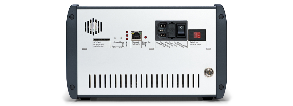
Voltage supply
- Worldwide voltage supply 90 – 250 V, 47 – 63 Hz
- Internally insulated
Connections
- 3 – for the winding connections or 3 phases to the test object
Measuring channels
- one measuring channel for voltage measurements
- one measuring channel for PD-tests via antenna or coupler
Test voltage
- up to max. 6 kV
The VoltageAnalyzer is an intelligent test probe.
It generates no surge- or high voltage, but measures it.
⇒ Find more details under Downloads.
Applications
Spannungsspitzen durch Frequenzumrichterbetrieb
Die nahezu rechteckigen Schaltflanken des Frequenzumrichters sind direkt am Ausgang des Umrichters noch sehr nahe an der optimalen rechteckigen Form. Das nachfolgende Bild zeigt die Impulsfolge der Spannung zwischen zwei Phasen direkt an den Klemmen des Umrichters. Man erkennt sehr deutlich die Impulse, die Pulsweitenmodulation sowie die negative und positive Halbwelle des „Sinus”.
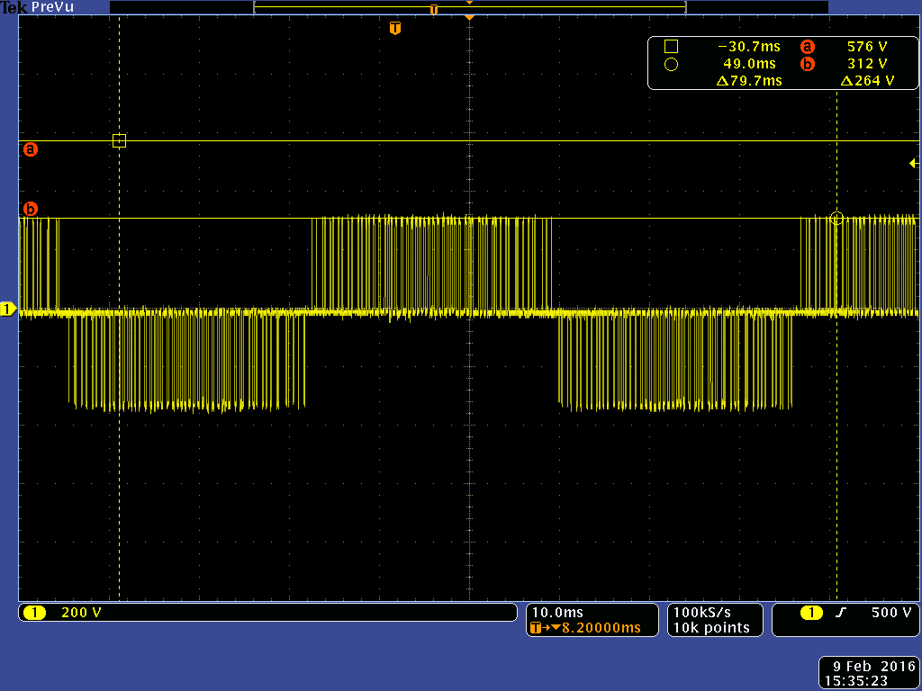
Die Spannungshöhe ergibt sich aus der AC-Versorgungsspannung des Frequenzumrichters. Da jeder Frequenzumrichter die Eingangsspannung zuerst gleichrichtet, gibt es in jedem Umrichter einen Gleichstromzwischenkreis, der sich auf die Eingangsspannung x √2 auflädt. Bei 230 V AC ergibt sich ein Wert von ca. 320 V DC und 400 V AC ein Wert von ca. 560 V DC. Das Bild zeigt einen Pegel von rund 315 V DC, was gut zu der 230 V AC Versorgung passt.
Der Motor ist über Leitungen mit dem Frequenzumrichter verbunden. Leitungen sind keine idealen elektrischen Bauteile, sondern bestehen aus Widerständen, Leitungsinduktivitäten und Kapazitäten. Dadurch wird der ideale Rechteckimpuls, der noch am Ausgang des Umrichters vorlag, auf dem Weg zum Motor stark verfälscht. Es entstehen sehr hohe Spannungsspitzen an den Flanken des Rechtecks. Diese werden umso ausgeprägter, je länger die Leitung zum Motor ist. Die nachfolgenden Bilder zeigen dies eindrucksvoll.
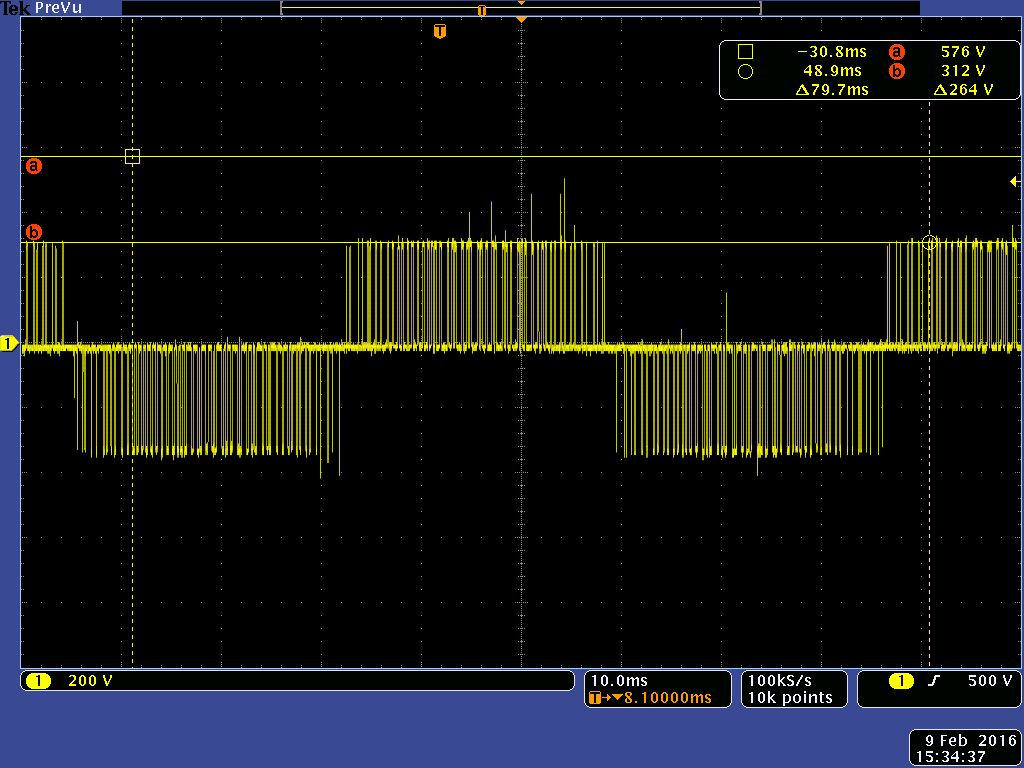
Leitung von 10 m Länge
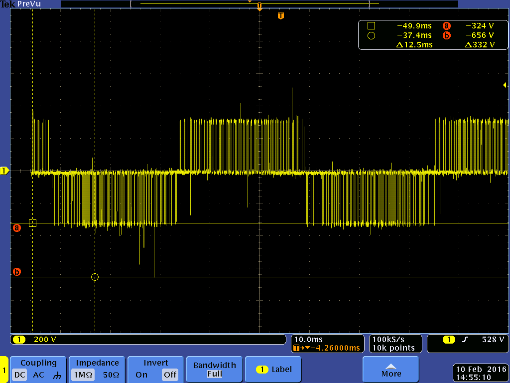
Leitung von 20 m Länge.
Die Spannungspitzen sind in diesem Beispiel nahezu doppelt so hoch, wie die normale Rechteckspannung. In der Praxis können noch viel höher Spannungsspitzen entstehen, die den Motor bei einer nicht frequenzumrichtertauglichen Isolation unweigerlich zerstören.
Das nächste Bild zeigt eine Spannungsspitze im Detail.
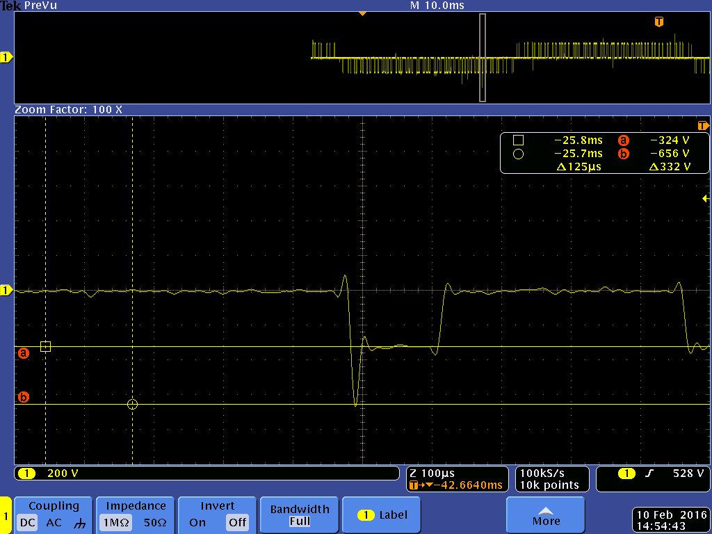
Deutlich ist zu erkennen, dass die Spitze nahezu doppelt so hoch ist, wie der eigentliche Rechteckimpuls.
For further information please do not hesitate to contact our technical sales under:
- +49 2372 901 25 40
- Email request
print preview
Product comparison
| type of tester |
| surge test |
| resistance |
| Induktivitäts-Kapazitätsprüfung |
| PE/GB |
| insulation |
| polarization index |
| high voltage AC |
| high voltage DC |
| partial discharge |
| function AC 1-phase |
| function AC 3-phase |
| sense of rotation |
| test terminals |
| test cover |
| automation |
| database |
| test plans |
| test results |
| communication |
| test report print-out |
| label print-out |
| scanner port |
| password protection |
| user management |
| operating system |
| display |
| battery mode |
| delivery |


 |
 |
 |
 |
 |
 |
 |
 |
 |
 |
 |
| MTC2 R7 | MotorAnalyzer1 | MotorAnalyzer2 R2 | MTC2 | MTC3 | VoltageAnalyzer | GLP3-M | EncoderAnalyzer | Dynamic MotorAnalyzer | PortaTest | Winding Machines |
|
THE surge tester · normative partial discharge · resistance · 4 wire measurement · Windows 10|11® · test report · PDF printing · network … |
motor Service · repairs · troubleshooting · maintenance · servicing · battery operation · PC software … |
multitool · 15 test methods · surge voltage 3 kV · resistance · inductance · capacitance · motor service · repair · fault detection · maintenance · battery mode · PC software … |
THE surge tester – up to 50 kV – plus normative partial discharge – resistance – 4-wire measurement – Windows10® – test protocol – PDF printing – network … |
Uncompromising ALL-IN-1 winding test for production · for all standard and special motors · for automotive drives · for coils of all kinds · automation · in-line partial discharge testing – worldwide networking · central data storage … |
high-precision test probe – direct surge voltage measurement at the winding – partial discharge – passive / active microwave antenna – up to 6 kV … |
modular ALL-IN-1 engine test system · no limits · customer specific · VDE/EN/UL/IEC … · production · automation · global networking · databases · statistics · data import/export · Windows® · complex systems … |
encoder and resolver testing/adjustment · encoder signal analysis · encoder power supply: 3 – 30 V · interface: HIPERFACE – EnDat – SSI – BiSS · BEMF measurement · repair · motor service · encoder production · servo motor production … |
online monitoring · fault analysis on the running motor · for mains and frequency converters · over 100 measured values · speed · torque · efficiency · unique oscilloscope · data recorder · trend analysis · battery operation · outdoor … |
insulation oil testing ⋅ fully automatic ⋅ dielectric strength ⋅ mobile ⋅ portable ⋅ on-site testing ⋅ laboratory testing ⋅ test voltages: 60 kV – 80 kV – 100 kV ⋅ various electrodes ⋅ integrated international test standards … |
coil winding machines for electric motors · for repair · for motor production · standard machines · special solutions … |
| read more | read more | read more | read more | read more | read more | read more | read more | read more | read more | read more |
|
surge testers winding testers |
winding testers motor & winding testers ALL-IN-1 |
surge testers winding testers motor & winding testers ALL-IN-1 |
surge testers winding testers |
surge testers winding testers |
— | electric motor testers ALL-IN-1 | encoder/resolver testers | electric motor testers ALL-IN-1 | insulating oil testers | winding machines |
|
0–6 kV 0–12 kV 0–15 kV |
— | 0–3 kV |
0–6 kV 0–12 kV 0–15 kV 0–25 kV 0–30 kV 0–40 kV 0–50 kV |
0–6 kV 0–15 kV |
0–6 kV | 0–6 kV | — | — | — | — |
| 4-wire measurement | 4-wire measurement | 4-wire measurement | 4-wire measurement | 4-wire measurement | — | 4-wire measurement | — | — | — | — |
|
nein ja |
— | — | — | — | — | — | — | — | — | — |
| — | — | — | — |
1–10 A˜ 6/12 Veff 1–30 A˜ 6/12 Veff |
— |
1–10 A˜ 6/12 Veff 1–30 A˜ 6/12 Veff custom |
— | — | — | — |
| Vmax like surge test | 0–3 kV ˭ | 0–6 kV ˭ | Vmax like surge test | Vmax like surge test | — |
0–1 kV ˭ max. 250 GΩ custom |
— | — | — | — |
| Vmax like surge test | Vmax like insulation test | Vmax like insulation test | Vmax like surge test | Vmax like surge test | — | — | — | — | — | — |
| 0–6 kV˜ max. 100 mA | — | — | 0–6 kV˜ max. 100 mA |
0–3 kV˜ max. 100 mA 0–6 kV˜ max. 100 mA 0–6 kV˜ max. 200 mA 0–6 kV˜ max. 1 A custom |
— |
0–3 kV˜ max. 100 mA 0–6 kV˜ max. 100 mA 0–6 kV˜ max. 200 mA custom |
— | — | — | — |
| 0–4 kV ˭ | 0–6 kV ˭ | — | custom | — | — | — | — | |||
| in case of surge test | — | — | in case of surge test |
in case of surge test in case of high voltage test AC in case of surge voltage and high voltage |
in case of surge test |
in case of surge test in case of high voltage test AC in case of surge voltage and high voltage |
— | — | — | — |
| — | — | — | — | — | — | according to your requirements | — | — | — | — |
| — | — | — | — | — | — | according to your requirements | — | according to your requirements | — | — |
| yes | yes | yes | yes | yes | — | yes | — | — | — | — |
|
T1, T2, T3, frame T1, T2, T3, Y, frame K1, K2, frame |
T1, T2, T3, frame | T1, T2, T3, frame |
T1, T2, T3, frame T1, T2, T3, Y, frame K1, K2, frame |
T1, T2, T3, frame T1, T2, T3, Y, frame 3, 6, 9, 12, 15, 18, ..., frame |
T1, T2, T3 |
L1, L2, L3, N, PE made to your specifications |
— | — | — | — |
| possible | — | — | possible | possible | — | possible | — | — | — | — |
|
with digital I/O with RS232 via SCHLEICH communication protocol with LAN via SCHLEICH communication protocol |
— | — |
with digital I/O with RS232 via SCHLEICH communication protocol with LAN via SCHLEICH communication protocol |
with digital I/O with RS232 via SCHLEICH communication protocol with LAN via SCHLEICH communication protocol with LAN via TCP/IP Socket Communication with PROFIBUS with PROFINET with EtherCAT with DeviceNet made to your specifications |
— |
with digital I/O with RS232 via SCHLEICH communication protocol with LAN via SCHLEICH communication protocol with LAN via SCPI commands with PROFIBUS with PROFINET with EtherCAT with CANopen with CAN Automotive with DeviceNet made to your specifications |
— | — | — | — |
|
ACCESS SQL |
— | — |
ACCESS SQL |
ACCESS SQL |
— |
ACCESS SQL ORACLE |
— | — | — | — |
|
stored in the tester stored in the tester and network import from PC, PLC, MES, ... |
— | — |
stored in the tester stored in the tester and network import from PC, PLC, MES, ... |
stored in the tester stored in the tester and network import from PC, PLC, MES, ... |
— |
stored in the tester stored in the tester and network import from PC, PLC, MES, ... |
— | — | — | — |
|
cached in the tester or network transfer to PC, PLC, MES, ... |
cached in the tester | cached in the tester |
cached in the tester or network transfer to PC, PLC, MES, ... |
cached in the tester or network transfer to PC, PLC, MES, ... |
— |
cached in the tester cached in the tester or network transfer to PC, PLC, MES, ... |
— | — | — | — |
|
with ERP, MES, PLC, CAQ, ... via LAN, WWW, OPC, ... |
— | — |
with ERP, MES, PLC, CAQ, ... via LAN, WWW, OPC, ... |
with ERP, MES, PLC, CAQ, ... via LAN, WWW, OPC, ... |
— |
with ERP, MES, PLC, CAQ, ... via LAN, WWW, OPC, ... |
— | — | — | — |
| yes | yes - via PC-Software | yes - via PC-Software | yes | yes | — | yes | — | yes | — | — |
| yes | — | — | yes | yes | — | yes | — | — | — | — |
| yes | — | — | yes | yes | — | yes | — | — | — | — |
| yes | — | yes | yes | yes | — | yes | — | yes | — | — |
| yes | — | — | yes | yes | — | yes | — | yes | — | — |
| Windows 10 11®-PC in the tester | SCHLEICH embedded | SCHLEICH embedded | Windows 10®-PC in the tester | Windows 10®-19"-Industrial PC integrated | — | Windows 10®-19"-Industrial PC integrated | — | Windows 10®-PC in the tester | — | — |
| PC monitor of any size | LCD 120 x 80 | touch color LCD 480 x 272 | PC monitor of any size | PC monitor of any size | — | PC monitor of any size | — | — | — | — |
| — | yes | yes | — | — | — | — | — | yes | — | — |
| on stock | on stock | on stock | on stock | order-related manufacturing | order-related manufacturing | order-related manufacturing | order-related manufacturing | order-related manufacturing | order-related manufacturing | order-related manufacturing |
SCHLEICH is a leading manufacturer of electrical safety, functional, winding and electric motor testing technology.
SCHLEICH is a world-renowned company that focuses on the development of innovative products in the field of testing technology for electrical products of all kinds.
From A to Z - everywhere SCHLEICH testing technology is in use worldwide. Our customers come from over 50 countries and regions. Everything is developed and produced in Germany.
Quality work - Made in Germany.
2022 - SCHLEICH is awarded for the fifth time as TOP100-Innovator
2016 - SCHLEICH released the first VoltageAnalyzer for measuring the real voltage directly at the winding terminals
2012 - SCHLEICH is awarded as TOP100-Innovator for the first time
2005 - SCHLEICH released the first stator tester with partial discharge test
1995 - SCHLEICH integrates touch-displays into testing devices as a world leader
1990 - SCHLEICH released the first safety and function tester with fully automatic integrated test terminal changeover
1987 - SCHLEICH released the first surge tester with PC-control under DOS and fully automatic integrated test terminal changeover
1985 - SCHLEICH released the first MotorAnalyzer
1982 - SCHLEICH focuses fully on electrical test engineering of electrical products
1952 - SCHLEICH is founded as a motor repair shop
Pioneering spirit, competence, curiosity, brand new technologies and innovations. This is what the 145-strong SCHLEICH team stands for - led by Martin & Jan-Philipp Lahrmann. Father & son. Your guarantors for long-term partnership.