Key-Facts
- The fastest partial discharge test of all times thanks to patented 50 Hz pulse-frequency technology
- Unsurpassed reliable winding fault detection due to the new, patented peak-to-peak measurement method
- The outstanding Full-HD touch display measures 15.6″ and enables optimal viewing and operation
- Fully integrated RLC test
- 4 test connections in four-wire technology + 1 frame connection
- Unrivaled fully automatic test method switching to all test connections
- Virtually unlimited compatibility thanks to built-in Windows 10® | 11® PC
- Various interfaces for remote control (Ethernet, RS232, fieldbus)
- Unique test method diversity thanks to modular configuration and expansion!
Variants
7 solutions for your testing task.
Please select the desired test method:

|
|
||||||||||||||||||||||||||||||||||||||||||||||||||
|
|
|
||||||||||||||||||||||||||||||||||||||||||||||||||

|
|
||||||||||||||||||||||||||||||||||||||||||||||||||
|
|
|
||||||||||||||||||||||||||||||||||||||||||||||||||
|
|
|
||||||||||||||||||||||||||||||||||||||||||||||||||
|
|
|
||||||||||||||||||||||||||||||||||||||||||||||||||
|
|
|
||||||||||||||||||||||||||||||||||||||||||||||||||
If you haven’t found the perfect test device yet, please do not hesitate to contact us.
We would be pleased to help you find a custom solution:

Product consultant
Are you looking for a personal consultation?
Please contact us directly: +49 2372 901 25 40
Or simply send us your questions via e-mail.
E-mail inquiryDescription
The new Vanguard.
The MTC2 R7 redefines surge voltage testing.
The latest hardware technologies paired with state-of-the-art .NetCore software come into play. This significantly increases the accuracy of the individual test methods and of the measurement speeds.
The MTC2 R7 is the high-end device for testing windings, coils and armatures.
| SCHLEICH PATENT: |
|
| The surge voltage test is capable of a pulse frequency of up to 50 Hz. The test time of the partial discharge inception voltages can thereby be reduced by up to 75 %. | |
| SCHLEICH PATENT: | |
| The SCHLEICH “peak to peak” method for the detection of voltage-dependent winding faults has been completely revised and enables highly sensitive fault detection even in the case of coils with very high numbers of windings, connected in series or parallel. |
The test methods
- Resistance test
- Inductance test
- Capacity test
- Insulation resistance test
- Insulation resistance test PI /DAR
- High voltage test DC
- Step voltage test
- High voltage test AC
- Surge voltage test
- Partial discharge test at surge voltage (conforms to standard)
- Drehfeldprüfung
Designed & Made in Germany.
As a mobile version with carrying handle or as a built-in version in a 19″ industrial rack. The MTC2 R7 fits your needs.
 |
 |
| Standard device for mobile and laboratory use | 19″ rack version |
Manifold connection possibilities
A test device can be as good as it is – it must fit into an established infrastructure and extend and refine existing possibilities. For this reason, the discreetly recessed connection panel of the MTC2 R7 standard device has been placed on the side to make it easily accessible. Whether you operate the device on a table or standing on the floor, all connections are conveniently accessible at all times.
The standard device:


*the standard device has built-in SHOCK absorbers to help protect the measurement equipment against vibrations.
| 0 | Power On/Off | Power supply | |
| 1 | Antenna input for partial discharge test | |
| 2 | Armature Booster | Accessories (signal input) | |
| 3 | Safety circuit 2-channel (PLe) | |
| 4 | Computer | 4 x USB 3.0 | 2 x DisplayPort | 2 x LAN | |
| 5 | Room/object temperature sensor | PT100, PT1000 and/or radiation pyrometer | |
| 6 | Rotary field probe connection | Div. accessories | |
| 7 | Warning light | |
| 8 | Result light | |
| 9 | Foot switch | |
| 10 | 4 measuring connections in four-wire technology + 1 frame connection | 9Pol |
Rack and 19″ version:
All connections are now located on the rear panel. This makes it very easy to integrate the MTC2 R7 into a 19″ rack. For optimal remote control, the device in this version has an additional PLC I/O interface, which is always installed as standard. Additionally RSS232, Ethernet or various field buses are expandable (Profinet, EtherCat or ProfiBus)..
| SPS I/O Interface | |
| Outputs | GO, NOGO, test running, ready0status and 8 * freely configurable outputs |
| Inputs | Start, 4 * freely configurable inputs |
5 Test leads
5 test leads give you the possibility to contact all relevant winding connections at once. The 3 phase connections as well as the star point (if available and accessible) are connected with 4 test leads. The fourth test connection at the star point gives you a unique increase in test accuracy. The fifth test connection is connected to the stator/motor housing. It is required for the insulation test between the winding and the laminated core.
Automatic test method switching
After connecting the device under test, the MTC2 R7 automatically tests on all 5 clamps. Thanks to the integrated test method switching, you no longer have to reconnect any connections by hand. This saves time and avoids errors.
Do you usually always need more than 4 measuring connections, e.g. to contact additional sensors or unconnected devices under test? Then an extension of the MTC2 R7 to a total of 8 measuring connections + frame is possible.

The surge voltage test
The surge voltage with standard-compliant edge steepness leaves no fault undetected. Modern automatic evaluations facilitate the subsequent fault analysis for you.
The MTC2 R7 features surge voltage testing with a pulse frequency of up to 50 Hz. This results in a considerable decrease in test cycle time, which is particularly advantageous in combination with the partial discharge inception voltage measurement (RPDIV). (optional extension)
learn more about surge voltage testing
Partial discharge test with surge voltage
The standard-compliant PD test can also be integrated. It gives you information about critical insulation weaknesses and the suitability for operation with frequency converters. Here SCHLEICH pursues two strategies to obtain good measurement results: both on the stator and on the fully assembled motor:
- Motors are measured with a coupler in the test lead.
- Stators are measured using an antenna.
Until now, the partial discharge inception voltage measurement was a particularly time-consuming test. For a 3-phase device under test, for example, this could take 8.5 minutes (depending on the parameterization of the test steps). With the new, patented surge voltage test of the MTC2 R7, it is possible to reduce test duration by approx. 75 % (with the same parameterization of the test steps). (optional extension)
learn more about partial discharge testing
Insulation resistance test
To achieve highly accurate measurement results for your resistance measurement comparison between the 3 phases, the resistance test is performed using four-wire technology. This automatically compensates for the resistances in the test leads. In addition, the MTC2 R7 detects the room temperature to compensate for any temperature influence. The resistance test including temperature compensation is always a part of the MTC2 R7.
By using SCHLEICH Kelvin clamps, compensation of the contact resistances at the clamping points to the winding is ensured. Only in this manner resistances of less than 10 Ω can be measured with high precision.
learn more about insulation resistance testing
High voltage test AC
In addition, the AC high voltage test can also be applied. It is also automatically switched to the device under test via the automatic test method switchover. (optional extension)
learn more about high voltage AC testing
Direction of rotation test
To check the rotating field of a stator, the MTC2 R7 simulates a rotating field supply at the three winding connections of a stator, connected in a star or delta connection. A special probe placed in the stator detects the sense of rotation which is then evaluated by the MTC2 R7. (optional extension)
learn more about sense of rotation testing
Armature test
A software assistant offers optimized support for the armature test. It guides you through the test so that no lamella will be missed. The manual test is performed using test probes or an armature adapter. The automatic test uses a fully automatic contacting adapter. Either the armature or the contacting adapter rotates to contact the lamellae precisely and reliably. An automatic position adjustment is built in for this purpose. Ask us – we can supply you with the complete solution to suit your armatures. (optional extension)
learn more about armature testing
Software
The new software is based on state-of-the-art .NET technology and has been completely redesigned. The MTC2 R7 features modern and clear views that enable intuitive operation. To ensure operation via touch during mobile use or in the workshop, a variety of settings can be displayed enlarged. Coupled with a big touch keyboard, the software allows operation even without mouse and keyboard.

Technology
Measurement technology advantages at a glance.
Autotest
- automatic stator, motor testing
- fully automatic fault analysis
Surge voltage
- 6, 12, 15, 25, 30, 40 and 50 kV
- rise time 100 – 500 ns in accordance with IEEE std 522-2004 (depending on the device under test)
- optional pulse frequency up to 50 Hz supported (depending on test voltage)
- automatic and manual surge voltage test
- 1-, 2- and 3-phase
- automatic evaluation
- 4 different evaluation methods incl. correlation (SCHLEICH patent)
- optional armature booster for testing DC armatures
High voltage DC
- 6, 12, 15, 25, 30, 40 and 50 kV
- manually, individually adjustable
- Auto programmable
- Step voltage measurement
Insulation resistance DC
- 6, 12, 15, 25, 30, 40 and 50 kV
- in accordance with VDE 0701
- 1 MΩ – 100 GΩ
- optional custom measuring range up to 1 teraohm
- Temperature compensation of the insulation resistance to 40 °C
PI (Polarisation Index) and DAR (Dielectric Absorption Ratio)
- 6, 12, 15, 25, 30, 40 and 50 kV
- automatic measurement
Partial discharge surge (optional)
- 6, 12, 15 and 25 kV
- in accordance with DIN EN 60034-18:2014
- measurement of
- PDIV – partial discharge inception voltage
- RPDIV – repetitive partial discharge inception voltage
- RPDEV – repetitive partial discharge extinction voltage
- PDEV – partial discharge extinction voltage
- Measurement via antenna – ideal for stators
- Measurement via coupler in the test line – ideal for motors
Resistance
- 1-, 2- and 3-phase
- 1 mΩ – 1 MΩ
- Determine resistance unbalance between the 3 phases
- High-precision four-wire measurement
- Room temperature compensation of the temperature-dependent Cu or Al resistors referred to 20 °C or 25 °C
High voltage AC (optional)
- up to 6 kV, 100 mA
- 1-, 2- and 3-phase
Connections
- 4 + 1 | 4 x Winding connections plus 1 x stator/motor housing
- 8 + 1 | 8 x Winding connections plus 1 x stator/motor housing (optional)
Automation
- digital I/Os, (inputs/outputs 24 V to PLC)
- Communication interfaces (optional)
- RS232 via SCHLEICH communication protocol
- LAN via SCHLEICH communication protocol
- LAN via TCP/IP
- EtherCat
- ProfiNet
- custom solutions …
Database
- MongoDB / PostgreSQL
- MS-SQL (optional)
Test plans
- Local storage
- Network storage
- Test plan/test parameter setting by a PC or other control system
- and more …
Test results
- Local storage
- Network storage
- Transmission to a PC or other controller
- Transmission to an MES
- Transmission to a CAQ system
- Transmission to SAP®
- and more …
Access control
- Power switch with key
- Password protection
- built-in user management
Power supply
- Suitable for worldwide use: voltage range 100 – 250 V, 47 – 63 Hz
Applications
MTC2 R7 test station with warning light

The many connection capabilities of the MTC2 R7 allow for a custom setup of the test area. Whether a warning and result light is used or a safety circuit (e.g. from a protective fence or test cover) is to be integrated, the MTC2 R7 allows for this with ease.
Motor repair
The MTC2 R7 comes ready for instant measurement. After a few motor parameters have been entered, the test can start. Either an autotest can be performed based on the entered motor parameters or a user-defined test sequence can be initiated.
Virtually all motor data including a picture can be stored. This simplifies the retrieval of motor data and the corresponding measurement results. The motor data are also printed directly on the SCHLEICH standard protocol in connection with the measurement results.
Motor repair | Manual testing of a rotor
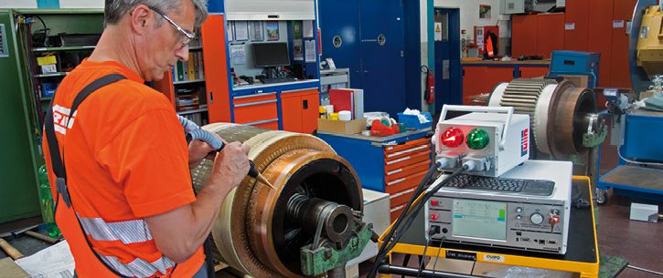
Using special test probes and an armature booster, the rotor is tested according to the lamellar method. This usually involves testing between two adjacent lamellae. A quarter or half circle measurement is also possible. The built-in armature assistant software reliably guides the operator through the test.
learn more about armature testing
Motor production
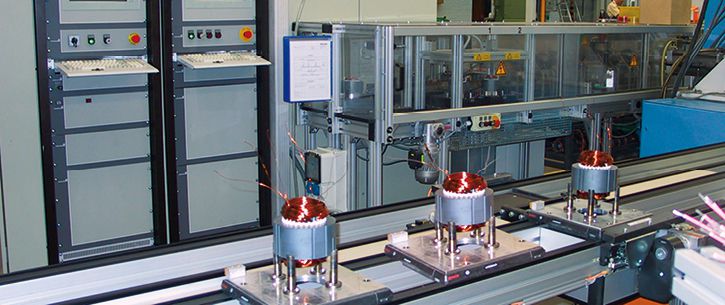
The MTC2 R7 can easily be incorporated into a production line. The housing measurements are based on a 19″ rack, which allows for seamless integration of the test device. The added interfaces enable full remote operation of the device by a PC control system.
For different types of devices under test, almost any number of test sequences can be stored in the MTC2 R7. These test sequences can be accessed and launched through an interface.
All test results can be accessed through an interface and can thereby be stored in a central database via the control PC. It is also possible to store the results locally on the test device or directly in a network.
More impressions
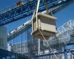 |
MTC2 on its way to a site
|
 |
Test on a faulty winding
|
 |
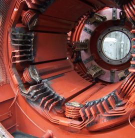
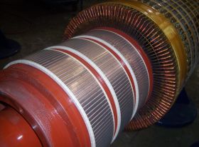
Testing of direct current rotors
|
 |
Testing without limits
|
For further information please do not hesitate to contact our technical sales under:
- +49 2372 901 25 40
- Email request
print preview
Product comparison
| type of tester |
| surge test |
| resistance |
| Induktivitäts-Kapazitätsprüfung |
| PE/GB |
| insulation |
| polarization index |
| high voltage AC |
| high voltage DC |
| partial discharge |
| function AC 1-phase |
| function AC 3-phase |
| sense of rotation |
| test terminals |
| test cover |
| automation |
| database |
| test plans |
| test results |
| communication |
| test report print-out |
| label print-out |
| scanner port |
| password protection |
| user management |
| operating system |
| display |
| battery mode |
| delivery |


|
|
 |
 |
 |
 |
 |
 |
 |
 |
 |
 |
| MTC2 R7 | MotorAnalyzer1 | MotorAnalyzer2 R2 | MTC2 | MTC3 | VoltageAnalyzer | GLP3-M | EncoderAnalyzer | Dynamic MotorAnalyzer | PortaTest | Winding Machines |
|
THE surge tester · normative partial discharge · resistance · 4 wire measurement · Windows 10|11® · test report · PDF printing · network … |
motor Service · repairs · troubleshooting · maintenance · servicing · battery operation · PC software … |
multitool · 15 test methods · surge voltage 3 kV · resistance · inductance · capacitance · motor service · repair · fault detection · maintenance · battery mode · PC software … |
THE surge tester – up to 50 kV – plus normative partial discharge – resistance – 4-wire measurement – Windows10® – test protocol – PDF printing – network … |
Uncompromising ALL-IN-1 winding test for production · for all standard and special motors · for automotive drives · for coils of all kinds · automation · in-line partial discharge testing – worldwide networking · central data storage … |
high-precision test probe – direct surge voltage measurement at the winding – partial discharge – passive / active microwave antenna – up to 6 kV … |
modular ALL-IN-1 engine test system · no limits · customer specific · VDE/EN/UL/IEC … · production · automation · global networking · databases · statistics · data import/export · Windows® · complex systems … |
encoder and resolver testing/adjustment · encoder signal analysis · encoder power supply: 3 – 30 V · interface: HIPERFACE – EnDat – SSI – BiSS · BEMF measurement · repair · motor service · encoder production · servo motor production … |
online monitoring · fault analysis on the running motor · for mains and frequency converters · over 100 measured values · speed · torque · efficiency · unique oscilloscope · data recorder · trend analysis · battery operation · outdoor … |
insulation oil testing ⋅ fully automatic ⋅ dielectric strength ⋅ mobile ⋅ portable ⋅ on-site testing ⋅ laboratory testing ⋅ test voltages: 60 kV – 80 kV – 100 kV ⋅ various electrodes ⋅ integrated international test standards … |
coil winding machines for electric motors · for repair · for motor production · standard machines · special solutions … |
| read more | read more | read more | read more | read more | read more | read more | read more | read more | read more | read more |
|
surge testers winding testers |
winding testers motor & winding testers ALL-IN-1 |
surge testers winding testers motor & winding testers ALL-IN-1 |
surge testers winding testers |
surge testers winding testers |
— | electric motor testers ALL-IN-1 | encoder/resolver testers | electric motor testers ALL-IN-1 | insulating oil testers | winding machines |
|
0–6 kV 0–12 kV 0–15 kV |
— | 0–3 kV |
0–6 kV 0–12 kV 0–15 kV 0–25 kV 0–30 kV 0–40 kV 0–50 kV |
0–6 kV 0–15 kV |
0–6 kV | 0–6 kV | — | — | — | — |
| 4-wire measurement | 4-wire measurement | 4-wire measurement | 4-wire measurement | 4-wire measurement | — | 4-wire measurement | — | — | — | — |
|
nein ja |
— | — | — | — | — | — | — | — | — | — |
| — | — | — | — |
1–10 A˜ 6/12 Veff 1–30 A˜ 6/12 Veff |
— |
1–10 A˜ 6/12 Veff 1–30 A˜ 6/12 Veff custom |
— | — | — | — |
| Vmax like surge test | 0–3 kV ˭ | 0–6 kV ˭ | Vmax like surge test | Vmax like surge test | — |
0–1 kV ˭ max. 250 GΩ custom |
— | — | — | — |
| Vmax like surge test | Vmax like insulation test | Vmax like insulation test | Vmax like surge test | Vmax like surge test | — | — | — | — | — | — |
| 0–6 kV˜ max. 100 mA | — | — | 0–6 kV˜ max. 100 mA |
0–3 kV˜ max. 100 mA 0–6 kV˜ max. 100 mA 0–6 kV˜ max. 200 mA 0–6 kV˜ max. 1 A custom |
— |
0–3 kV˜ max. 100 mA 0–6 kV˜ max. 100 mA 0–6 kV˜ max. 200 mA custom |
— | — | — | — |
| 0–4 kV ˭ | 0–6 kV ˭ | — | custom | — | — | — | — | |||
| in case of surge test | — | — | in case of surge test |
in case of surge test in case of high voltage test AC in case of surge voltage and high voltage |
in case of surge test |
in case of surge test in case of high voltage test AC in case of surge voltage and high voltage |
— | — | — | — |
| — | — | — | — | — | — | according to your requirements | — | — | — | — |
| — | — | — | — | — | — | according to your requirements | — | according to your requirements | — | — |
| yes | yes | yes | yes | yes | — | yes | — | — | — | — |
|
T1, T2, T3, frame T1, T2, T3, Y, frame K1, K2, frame |
T1, T2, T3, frame | T1, T2, T3, frame |
T1, T2, T3, frame T1, T2, T3, Y, frame K1, K2, frame |
T1, T2, T3, frame T1, T2, T3, Y, frame 3, 6, 9, 12, 15, 18, ..., frame |
T1, T2, T3 |
L1, L2, L3, N, PE made to your specifications |
— | — | — | — |
| possible | — | — | possible | possible | — | possible | — | — | — | — |
|
with digital I/O with RS232 via SCHLEICH communication protocol with LAN via SCHLEICH communication protocol |
— | — |
with digital I/O with RS232 via SCHLEICH communication protocol with LAN via SCHLEICH communication protocol |
with digital I/O with RS232 via SCHLEICH communication protocol with LAN via SCHLEICH communication protocol with LAN via TCP/IP Socket Communication with PROFIBUS with PROFINET with EtherCAT with DeviceNet made to your specifications |
— |
with digital I/O with RS232 via SCHLEICH communication protocol with LAN via SCHLEICH communication protocol with LAN via SCPI commands with PROFIBUS with PROFINET with EtherCAT with CANopen with CAN Automotive with DeviceNet made to your specifications |
— | — | — | — |
|
ACCESS SQL |
— | — |
ACCESS SQL |
ACCESS SQL |
— |
ACCESS SQL ORACLE |
— | — | — | — |
|
stored in the tester stored in the tester and network import from PC, PLC, MES, ... |
— | — |
stored in the tester stored in the tester and network import from PC, PLC, MES, ... |
stored in the tester stored in the tester and network import from PC, PLC, MES, ... |
— |
stored in the tester stored in the tester and network import from PC, PLC, MES, ... |
— | — | — | — |
|
cached in the tester or network transfer to PC, PLC, MES, ... |
cached in the tester | cached in the tester |
cached in the tester or network transfer to PC, PLC, MES, ... |
cached in the tester or network transfer to PC, PLC, MES, ... |
— |
cached in the tester cached in the tester or network transfer to PC, PLC, MES, ... |
— | — | — | — |
|
with ERP, MES, PLC, CAQ, ... via LAN, WWW, OPC, ... |
— | — |
with ERP, MES, PLC, CAQ, ... via LAN, WWW, OPC, ... |
with ERP, MES, PLC, CAQ, ... via LAN, WWW, OPC, ... |
— |
with ERP, MES, PLC, CAQ, ... via LAN, WWW, OPC, ... |
— | — | — | — |
| yes | yes - via PC-Software | yes - via PC-Software | yes | yes | — | yes | — | yes | — | — |
| yes | — | — | yes | yes | — | yes | — | — | — | — |
| yes | — | — | yes | yes | — | yes | — | — | — | — |
| yes | — | yes | yes | yes | — | yes | — | yes | — | — |
| yes | — | — | yes | yes | — | yes | — | yes | — | — |
| Windows 10 11®-PC in the tester | SCHLEICH embedded | SCHLEICH embedded | Windows 10®-PC in the tester | Windows 10®-19"-Industrial PC integrated | — | Windows 10®-19"-Industrial PC integrated | — | Windows 10®-PC in the tester | — | — |
| PC monitor of any size | LCD 120 x 80 | touch color LCD 480 x 272 | PC monitor of any size | PC monitor of any size | — | PC monitor of any size | — | — | — | — |
| — | yes | yes | — | — | — | — | — | yes | — | — |
| on stock | on stock | on stock | on stock | order-related manufacturing | order-related manufacturing | order-related manufacturing | order-related manufacturing | order-related manufacturing | order-related manufacturing | order-related manufacturing |
SCHLEICH is a leading manufacturer of electrical safety, functional, winding and electric motor testing technology.
SCHLEICH is a world-renowned company that focuses on the development of innovative products in the field of testing technology for electrical products of all kinds.
From A to Z - everywhere SCHLEICH testing technology is in use worldwide. Our customers come from over 50 countries and regions. Everything is developed and produced in Germany.
Quality work - Made in Germany.
2022 - SCHLEICH is awarded for the fifth time as TOP100-Innovator
2016 - SCHLEICH released the first VoltageAnalyzer for measuring the real voltage directly at the winding terminals
2012 - SCHLEICH is awarded as TOP100-Innovator for the first time
2005 - SCHLEICH released the first stator tester with partial discharge test
1995 - SCHLEICH integrates touch-displays into testing devices as a world leader
1990 - SCHLEICH released the first safety and function tester with fully automatic integrated test terminal changeover
1987 - SCHLEICH released the first surge tester with PC-control under DOS and fully automatic integrated test terminal changeover
1985 - SCHLEICH released the first MotorAnalyzer
1982 - SCHLEICH focuses fully on electrical test engineering of electrical products
1952 - SCHLEICH is founded as a motor repair shop
Pioneering spirit, competence, curiosity, brand new technologies and innovations. This is what the 145-strong SCHLEICH team stands for - led by Martin & Jan-Philipp Lahrmann. Father & son. Your guarantors for long-term partnership.