EncoderAnalyzer
Inspecting and adjusting encoders
Check and adjust all types of electric motor encoders with the SCHLEICH-EncoderAnalyzer.
And it’s as easy as that: Connect the encoder to the EncoderAnalyzer directly or via a connection box and enter the technical data of the encoder.
The EncoderAnalyzer supplies the encoder with the necessary voltage, checks the current consumption and measures all signals.
On the PC screen, the EncoderAnalyzer shows you a clear analysis and possible encoder errors. In addition, you receive a meaningful graphical representation of all encoder signals, just like an oscilloscope.
For the adjustment of resolvers and Hall sensors, the EncoderAnalyzer also measures the EMF (BEMF) of the motor in order to provide you with the best possible support for angle adjustment of the encoder.
The EncoderAnalyzer is the optimal single device for repair and production.
The EncoderAnalyzer can also be integrated directly into SCHLEICH motor test benches.
Please note that the EncoderAnalyzer is offered exclusively for integration into a motor test station. It is not possible to purchase a stand-alone device.
Product consultant

Key-Facts

All in One – Encoder analysis.
- Encoder analysis without special knowledge
- Automatic inspection of all encoder signals
- Inspection of all signal pulses per revolution
- Determination of number of pulses per revolution
- Inspection of all 90 degree-phase shifts between signals per revolution
- automatic inspection of all signal voltages per revolution
- Sense of rotation and encoder speed
- Angle fault per revolution
- Angle balance of rotary encoders
- EMF-measurement at all three motor phases to adjust resolvers, encoders or hall elements
- Storing the angle offset in the rotary encoder via data interface
- EMF-measurement to determine the ke-value (voltage constant) during run-out and standardization to 1000 rpm
- EMF-symmetry measurements during run-out
- Incremental encoder test with A – /A – B – /B – Z – /Z channels
- Sine- Cosine-rotary encoder test with sin – /sin – cos – /cos – N – /N channels
- Resolver-tests
- Hall element-test, evaluation of the three commutation signals
- Encoder interfaces via SSi, EnDat, Hiperface
- Measuring module with 6 or 12 high-speed-measuring channels
- Integrated adjustable voltage supply for encoders
- Integrated reference signal source for resolvers
- Windows®-Software to evaluate the measuring signals
- Measuring signals displayed similar to an oscilloscope
- SQL-database for encoder types, sorted by manufacturer and type
- Multilingual user interface
Variants
4 solutions for your testing task.
Please select the desired test method:

|
|
|||
|
|
|
|||
|
|
|
|||
|
|
|
|||
If you haven’t found the perfect test device yet, please do not hesitate to contact us.
We would be pleased to help you find a custom solution:

Product consultant
Are you looking for a personal consultation?
Please contact us directly: +49 2372 901 25 40
Or simply send us your questions via e-mail.
E-mail inquiryDescription
The functional principle – genious and simple.
Modern drives are often equipped with rotary encoders. For the operator, a detailed inspection is made difficult due to the large diversity of encoders in the market. This applies in particular for repairers of electric motors but also for analyses in production. An extensive inspection without special measuring technology is not possible.
The EncoderAnalyzer offers valuable services by simplifying the encoder inspection as it supplies the encoder with voltage and measures all signals. Afterwards they are automatically evaluated. The result is indicated either as a clear GO (o.k. ) or a clear NOGO (not o.k.).
The following rotary encoders and sensor systems may be inspected:
- Incremental square wave encoders with A, /A, B, /B, N, /N, U, /U, V, /V, W, /W6-channel EncoderAnalyzer
-
Sine-cosine encoders with sin, /sin, cos, /cos, N, /N
-
Hall elements with A, /A, B, /B, N, /N
-
Hall elements with U, /U, V, /V, W, /W
-
Commutation signals / block commutation
-
Multiturn-absolute encoders with SSi- and Hiperface-interface
-
optional resolvers
-
optional 3-phase motor current measurment during operation
-
optional EMF-voltage measurement up to 700V
-
optional resolver adjustment regarding the moto´s EMF
-
optional programming the rotary encoder´s angle offset
The functional principle.
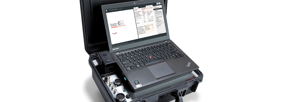
The EncoderAnalyzer consists of two components: The measuring module and the analysing software, which is to be installed on a PC.
The measuring module provides a connection for the encoders to be inspected. Furthermore, additional components for supplementary measuring functions may be connected to the measuring module.
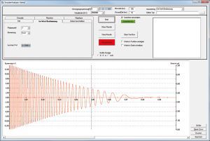
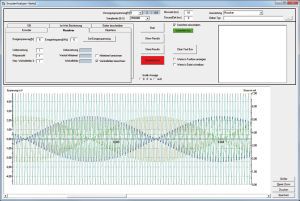
The measuring module performs the tests. For this, it determines millions of measuring values during one revolution and transfers them to a PC. The communication between measuring module and PC is done by a Gigabit-Ethernet connection. By means of the analyzing software the measured results are automatically evaluated. At the end of an inspection the software presents the result on the screen. For a better understanding, errors detected at a broken rotary encoder, are graphically displayed like in an oscilloscope.
The test results are stored in a database. If requested, a detailed test report may be printed.
Connecting the rotary encoder
The rotary encoder to be inspected is connected with the measuring module by a measuring lead. On the measuring module´s front side up to 2 measuring sockets are available for the connection of the measuring leads. verbunden. The number of measuring sockets depends on the ordered options. The EncoderAnalyzer with all 12 measuring channels is equipped with 2 measuring sockets.
A voltage supply of 3…30 V is also integrated in the EncoderAnalyzer. Depending on the encoder, voltage level and maximum permissible power consumption are entered by the operator via software input. During the measurement the EncoderAnalyzer monitors the power consumption. In case the maximum permissible value is exceeded, the voltage supply is automatically switched off.
- Measuring socket MU for
- three high-voltage measuring inputs
- Measuring socket MI for
- three current measuring inputs for current clamps
- Measuring socket MP for
- resolvers
- Measuring socket ME for
- Incremental square-wave encoders
- Sine-cosine encoders
- Hall elements
- Commutation signals/ Block commutation
- Encoder´s voltage supply
- Communication – and programming interface
The analysis software
The fast and intelligent measuring technology and the user-friendly, intuitive analysis software are perfectly matched with each other. Only a few settings and selections are sufficient, to configure the measurement for the encoder to be tested.
The extensive evaluations lead to clear and easy-understandable results. Special or detailed knowhow is not necessary while dealing with the analysis software. The software helps and supports during the connection and evaluation of encoders.
As supplement to the encoder analysis the software also assists during the angle adjustment of rotary encoders. No matter, if the rotary encoder needs to be adjusted by mechanical turning or if only the angle offset needs to be determined, the software graphically supports the operator during the adjustment. Depending on the encoder type and the EncoderAnalyzer´s equipment, the offset angle may also be written in the rotary encoder.
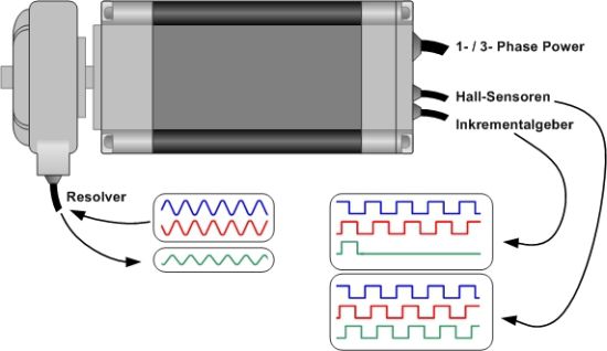
EMF-measurment Resolver signal
Measuring principles for the encoder inspection
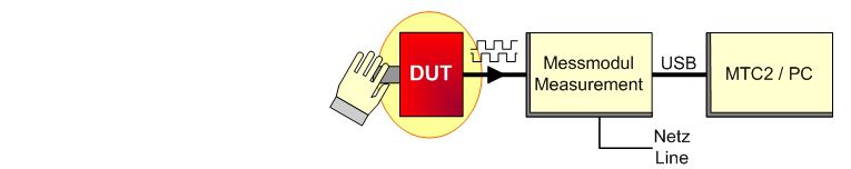
1. Rotary encoder- / Resolver test
The rotary encoder is connected with the measuring module with an appropriate connection lead. Afterwards you manually turn the encoder´s axis. The arising impulses are digitized and evaluated by the measuring module.
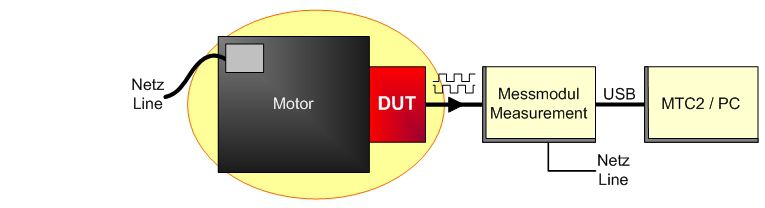
2. Rotary encoder- / Resolver test together with the motor
The rotary encoder mounted on the motor is connected with the measuring module with an appropriate connection lead. Afterwards the motor is directly operated from the mains or via a frequency converter. The arising impulses are digitized and evaluated by the measuring module.
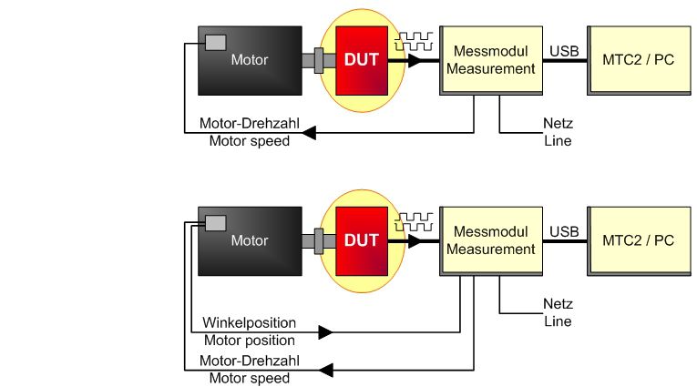
3. Rotary encoder- / Resolver test by means of a test installation
In a special SCHLEICH-test installation the rotary encoder is mechanically coupled with a small drive motor. Via an appropriate connection lead it is connected with the measuring module. For testing purposes the module actuates the drive motor. The arising impulses are digitized and evaluated by the measuring module. Depending on the encoder to be tested the motor´s angle position may also be determined.
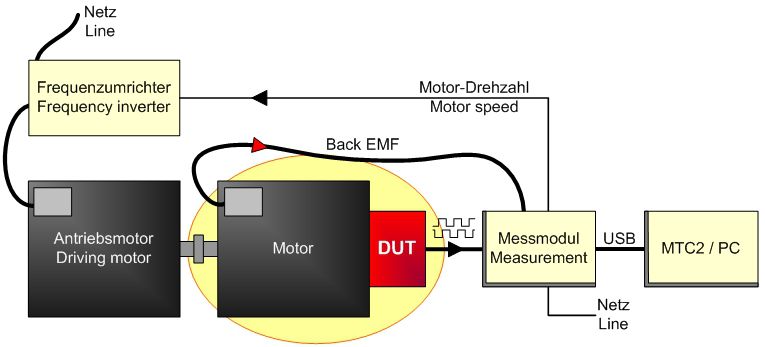
4. Resolver- / Hall element adjustment
For the adjustment the resolver, which is still connected with the motor, is additionally connected with the measuring module via an appropriate connection lead. Furthermore the motor is mechanically coupled by a drive motor. Afterwards the drive motor is directly operated from the mains or, better, by a frequency converter. The arising pulses and the Back-EMF induced in the windings are digitized and evaluated by the measuring module. The measuring module derives the adjustment-information from the measured values which is also indicated on the screen.
Voltage supply for the encoder
For testing purposes, the encoder has to be supplied with DC-voltage which is generated in the measuring module and in the requested voltage level. The supply voltage is shortcircuit proof and the encoder´s power consumption is also inspected. In case the power consumption is too high, the measuring module automatically switches-off the supply voltage due to safety reasons.
Database
The software is equipped with a database with storage capacity for thousands of encoders and resolver.
For the inspection of an encoder, the corresponding data has to be contained in the database. The data consists of relevant information as e.g. the encoder type, the supply voltage level, the pin assignment and so on. Based on this information, the software assists you regarding the suitable connection cable and how to properly connect the encoder.
Furthermore the database contains even more information. Although they are not important for the measurements, they inform about further details of the encoder.
Technology
Benefits at a glance.
General information
- Worldwide voltage supply 90–250 V, 47–63 Hz
- Dimensions W 20 x D 20 x H 5 cm
- weight 1 kg
- Operating temperature 10°–50° Celsius
- Storing temperature-20°–60° Celsius
Encoder
- Measuring inputs
- 6 x or optional 12 x analog inputs
- Measuring range 0–30 V
- Measuring signals A – /A – B – /B – Z – /Z
- Measuring signals sin – /sin – cos – /cos – ref – /ref
- Measuring signals K1 – /K1 – K2 – /K2 – K3 – /K3
Resolver
- Excitation output
- 1 x analog output
- Voltage range 0-10 V
- Frequency range1-10 KHz
- Measuring inputs
- 2 x analog inputs
- Measuring range 0–30 V
- Measuring signals sin – /sin – cos – /cos
Single- and Multiturn encoders
- Measuring inputs
- 6 x analog inputs
- Measuring range 0–30 V
- Measuring signals sin – /sin – cos – /cos – ref – /ref
- Protocol data interfaces
- Hiperface
- SSi
- EnDat 2.2 – bidirectional
EMF-Measurement
- Measuring inputs
- 3 x analog inputs
- measuring range 0–700 Veff
- internal virtual neutral point
- fuses integrated in the tester
- fuses integrated in the test probes
⇒ More details available under Downloads.
Applications
Encoder inspection in the workshop.
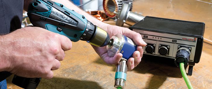
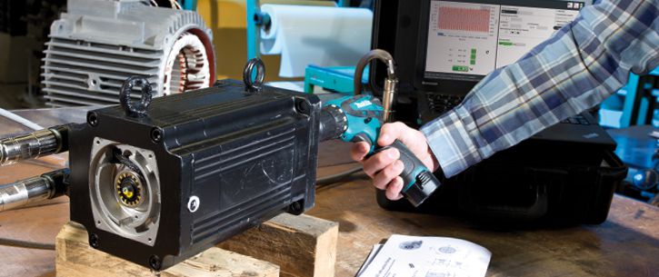
The EncoderAnalyzer is only able to inspect encoders with rotating shaft. For this, the encoder may be directly driven by the motor at which the encoder is installed.
But also in case the encoder is to be inspected separately, it has to be driven by constant speed. For this, as example, a cordless screwdriver can be used.
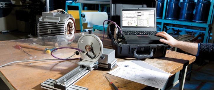
As an alternative, the encoder/ resolver may also be inspected separately on a small test stand. The test stand is equipped with a small motor which drives the encoder with selectable speed. The EncoderAnalyzer collects all signals and determines all parameters. In case target values are entered in the EncoderAnalyzer, an automatic target-actual comparison is done by the software, followed by an evaluation.
For further information please do not hesitate to contact our technical sales under:
- +49 2372 901 25 40
- Email request
print preview
Product comparison
| type of tester |
| surge test |
| resistance |
| Induktivitäts-Kapazitätsprüfung |
| PE/GB |
| insulation |
| polarization index |
| high voltage AC |
| high voltage DC |
| partial discharge |
| function AC 1-phase |
| function AC 3-phase |
| sense of rotation |
| test terminals |
| test cover |
| automation |
| database |
| test plans |
| test results |
| communication |
| test report print-out |
| label print-out |
| scanner port |
| password protection |
| user management |
| operating system |
| display |
| battery mode |
| delivery |


 |
 |
 |
 |
 |
 |
 |
|
 |
 |
 |
| MTC2 R7 | MotorAnalyzer1 | MotorAnalyzer2 R2 | MTC2 | MTC3 | VoltageAnalyzer | GLP3-M | EncoderAnalyzer | Dynamic MotorAnalyzer | PortaTest | Winding Machines |
|
THE surge tester · normative partial discharge · resistance · 4 wire measurement · Windows 10|11® · test report · PDF printing · network … |
motor Service · repairs · troubleshooting · maintenance · servicing · battery operation · PC software … |
multitool · 15 test methods · surge voltage 3 kV · resistance · inductance · capacitance · motor service · repair · fault detection · maintenance · battery mode · PC software … |
THE surge tester – up to 50 kV – plus normative partial discharge – resistance – 4-wire measurement – Windows10® – test protocol – PDF printing – network … |
Uncompromising ALL-IN-1 winding test for production · for all standard and special motors · for automotive drives · for coils of all kinds · automation · in-line partial discharge testing – worldwide networking · central data storage … |
high-precision test probe – direct surge voltage measurement at the winding – partial discharge – passive / active microwave antenna – up to 6 kV … |
modular ALL-IN-1 engine test system · no limits · customer specific · VDE/EN/UL/IEC … · production · automation · global networking · databases · statistics · data import/export · Windows® · complex systems … |
encoder and resolver testing/adjustment · encoder signal analysis · encoder power supply: 3 – 30 V · interface: HIPERFACE – EnDat – SSI – BiSS · BEMF measurement · repair · motor service · encoder production · servo motor production … |
online monitoring · fault analysis on the running motor · for mains and frequency converters · over 100 measured values · speed · torque · efficiency · unique oscilloscope · data recorder · trend analysis · battery operation · outdoor … |
insulation oil testing ⋅ fully automatic ⋅ dielectric strength ⋅ mobile ⋅ portable ⋅ on-site testing ⋅ laboratory testing ⋅ test voltages: 60 kV – 80 kV – 100 kV ⋅ various electrodes ⋅ integrated international test standards … |
coil winding machines for electric motors · for repair · for motor production · standard machines · special solutions … |
| read more | read more | read more | read more | read more | read more | read more | read more | read more | read more | read more |
|
surge testers winding testers |
winding testers motor & winding testers ALL-IN-1 |
surge testers winding testers motor & winding testers ALL-IN-1 |
surge testers winding testers |
surge testers winding testers |
— | electric motor testers ALL-IN-1 | encoder/resolver testers | electric motor testers ALL-IN-1 | insulating oil testers | winding machines |
|
0–6 kV 0–12 kV 0–15 kV |
— | 0–3 kV |
0–6 kV 0–12 kV 0–15 kV 0–25 kV 0–30 kV 0–40 kV 0–50 kV |
0–6 kV 0–15 kV |
0–6 kV | 0–6 kV | — | — | — | — |
| 4-wire measurement | 4-wire measurement | 4-wire measurement | 4-wire measurement | 4-wire measurement | — | 4-wire measurement | — | — | — | — |
|
nein ja |
— | — | — | — | — | — | — | — | — | — |
| — | — | — | — |
1–10 A˜ 6/12 Veff 1–30 A˜ 6/12 Veff |
— |
1–10 A˜ 6/12 Veff 1–30 A˜ 6/12 Veff custom |
— | — | — | — |
| Vmax like surge test | 0–3 kV ˭ | 0–6 kV ˭ | Vmax like surge test | Vmax like surge test | — |
0–1 kV ˭ max. 250 GΩ custom |
— | — | — | — |
| Vmax like surge test | Vmax like insulation test | Vmax like insulation test | Vmax like surge test | Vmax like surge test | — | — | — | — | — | — |
| 0–6 kV˜ max. 100 mA | — | — | 0–6 kV˜ max. 100 mA |
0–3 kV˜ max. 100 mA 0–6 kV˜ max. 100 mA 0–6 kV˜ max. 200 mA 0–6 kV˜ max. 1 A custom |
— |
0–3 kV˜ max. 100 mA 0–6 kV˜ max. 100 mA 0–6 kV˜ max. 200 mA custom |
— | — | — | — |
| 0–4 kV ˭ | 0–6 kV ˭ | — | custom | — | — | — | — | |||
| in case of surge test | — | — | in case of surge test |
in case of surge test in case of high voltage test AC in case of surge voltage and high voltage |
in case of surge test |
in case of surge test in case of high voltage test AC in case of surge voltage and high voltage |
— | — | — | — |
| — | — | — | — | — | — | according to your requirements | — | — | — | — |
| — | — | — | — | — | — | according to your requirements | — | according to your requirements | — | — |
| yes | yes | yes | yes | yes | — | yes | — | — | — | — |
|
T1, T2, T3, frame T1, T2, T3, Y, frame K1, K2, frame |
T1, T2, T3, frame | T1, T2, T3, frame |
T1, T2, T3, frame T1, T2, T3, Y, frame K1, K2, frame |
T1, T2, T3, frame T1, T2, T3, Y, frame 3, 6, 9, 12, 15, 18, ..., frame |
T1, T2, T3 |
L1, L2, L3, N, PE made to your specifications |
— | — | — | — |
| possible | — | — | possible | possible | — | possible | — | — | — | — |
|
with digital I/O with RS232 via SCHLEICH communication protocol with LAN via SCHLEICH communication protocol |
— | — |
with digital I/O with RS232 via SCHLEICH communication protocol with LAN via SCHLEICH communication protocol |
with digital I/O with RS232 via SCHLEICH communication protocol with LAN via SCHLEICH communication protocol with LAN via TCP/IP Socket Communication with PROFIBUS with PROFINET with EtherCAT with DeviceNet made to your specifications |
— |
with digital I/O with RS232 via SCHLEICH communication protocol with LAN via SCHLEICH communication protocol with LAN via SCPI commands with PROFIBUS with PROFINET with EtherCAT with CANopen with CAN Automotive with DeviceNet made to your specifications |
— | — | — | — |
|
ACCESS SQL |
— | — |
ACCESS SQL |
ACCESS SQL |
— |
ACCESS SQL ORACLE |
— | — | — | — |
|
stored in the tester stored in the tester and network import from PC, PLC, MES, ... |
— | — |
stored in the tester stored in the tester and network import from PC, PLC, MES, ... |
stored in the tester stored in the tester and network import from PC, PLC, MES, ... |
— |
stored in the tester stored in the tester and network import from PC, PLC, MES, ... |
— | — | — | — |
|
cached in the tester or network transfer to PC, PLC, MES, ... |
cached in the tester | cached in the tester |
cached in the tester or network transfer to PC, PLC, MES, ... |
cached in the tester or network transfer to PC, PLC, MES, ... |
— |
cached in the tester cached in the tester or network transfer to PC, PLC, MES, ... |
— | — | — | — |
|
with ERP, MES, PLC, CAQ, ... via LAN, WWW, OPC, ... |
— | — |
with ERP, MES, PLC, CAQ, ... via LAN, WWW, OPC, ... |
with ERP, MES, PLC, CAQ, ... via LAN, WWW, OPC, ... |
— |
with ERP, MES, PLC, CAQ, ... via LAN, WWW, OPC, ... |
— | — | — | — |
| yes | yes - via PC-Software | yes - via PC-Software | yes | yes | — | yes | — | yes | — | — |
| yes | — | — | yes | yes | — | yes | — | — | — | — |
| yes | — | — | yes | yes | — | yes | — | — | — | — |
| yes | — | yes | yes | yes | — | yes | — | yes | — | — |
| yes | — | — | yes | yes | — | yes | — | yes | — | — |
| Windows 10 11®-PC in the tester | SCHLEICH embedded | SCHLEICH embedded | Windows 10®-PC in the tester | Windows 10®-19"-Industrial PC integrated | — | Windows 10®-19"-Industrial PC integrated | — | Windows 10®-PC in the tester | — | — |
| PC monitor of any size | LCD 120 x 80 | touch color LCD 480 x 272 | PC monitor of any size | PC monitor of any size | — | PC monitor of any size | — | — | — | — |
| — | yes | yes | — | — | — | — | — | yes | — | — |
| on stock | on stock | on stock | on stock | order-related manufacturing | order-related manufacturing | order-related manufacturing | order-related manufacturing | order-related manufacturing | order-related manufacturing | order-related manufacturing |
SCHLEICH is a leading manufacturer of electrical safety, functional, winding and electric motor testing technology.
SCHLEICH is a world-renowned company that focuses on the development of innovative products in the field of testing technology for electrical products of all kinds.
From A to Z - everywhere SCHLEICH testing technology is in use worldwide. Our customers come from over 50 countries and regions. Everything is developed and produced in Germany.
Quality work - Made in Germany.
2022 - SCHLEICH is awarded for the fifth time as TOP100-Innovator
2016 - SCHLEICH released the first VoltageAnalyzer for measuring the real voltage directly at the winding terminals
2012 - SCHLEICH is awarded as TOP100-Innovator for the first time
2005 - SCHLEICH released the first stator tester with partial discharge test
1995 - SCHLEICH integrates touch-displays into testing devices as a world leader
1990 - SCHLEICH released the first safety and function tester with fully automatic integrated test terminal changeover
1987 - SCHLEICH released the first surge tester with PC-control under DOS and fully automatic integrated test terminal changeover
1985 - SCHLEICH released the first MotorAnalyzer
1982 - SCHLEICH focuses fully on electrical test engineering of electrical products
1952 - SCHLEICH is founded as a motor repair shop
Pioneering spirit, competence, curiosity, brand new technologies and innovations. This is what the 145-strong SCHLEICH team stands for - led by Martin & Jan-Philipp Lahrmann. Father & son. Your guarantors for long-term partnership.