The synchronous motor in generator operation
When a permanently or separately excited synchronous motor is in generator operation, it generates a three-phase voltage typical for the motor at the three motor connection leads. The voltage level of the machine results from its:
- magnetic properties
- winding characteristics
- rotational speed
The frequency of the voltage is determined by the speed and number of poles of the machine.
Rotational speed-dependent voltage level
This generated voltage is often used for specification and qualitative evaluation of the machine. Since the voltage level is speed-dependent, the speed is defined as the condition for the test. The test rotational speed is usually 1000 min-1. Logically, the three phase voltages should have only a very small deviation from each other.
ke-value – voltage constant
The measured voltage is often referred to as ke-value or voltage constant. Some manufacturers also indicate this value on the motor’s nameplate. This information can almost always be found in the technical data.
The unit of the ke-value is V/rpm or V/Krpm. But you can also find specifications like mV · min or V · s. These values are all correlated and can be converted among each other.
Varying from manufacturer to manufacturer, the measurement can be performed either between the phases or from one phase to the neutral point. Since synchronous machines usually do not have a brought-out neutral point, an artificial external virtual neutral point can be used for measurement.
Temperature dependence of the ke-value
Please note: The ke-value is dependent on temperature. Therefore, if necessary, a temperature compensation of the ke-value is carried out taking into account the magnetic rotor material.

The three measuring principles
The basis for measuring the ke-value is an engine speed defined by the manufacturer, e.g. 1000 min-1. In the simplest case, the test object is driven by a drive motor at the desired speed for testing.

❶ In detail, the solution can be such that a drive motor controlled by an inverter is brought to a speed of exactly 1000 min-1. Using appropriate measuring technology, the three voltages are measured on the test object and the ke-values are determined.
The disadvantage of this solution is that a mechanical coupling between the drive motor and the test object has to be established for testing. This can be too time-consuming in production and thus too cost-intensive.

This type of measurement at constant speed shows the typical voltage shape on the test object:

❷ A much more elegant solution is to use an inverter to bring the synchronous motor under test to a desired speed, then to separate it from the inverter and to determine the ke-value during the coast down.
During coasting, both the voltage level and the frequency change continuously. A stationary measurement at a fixed speed is not possible during spin-out – however, these two effects can be mathematically compensated for by means of a special SCHLEICH method!
The test result is again a voltage related to the desired speed. With this measuring method you do not only obtain very precise, but also easily repeatable measuring results.
Since the mechanical coupling between a drive machine and the test object is not necessary, this solution has an immense advantage. There is no additional work for the operator and it is extremely time efficient.
Depending on the converter used, the test object can be operated sensorless, i.e. without encoder, but also with encoder.

❸ In laboratories and/or for repair as well as for fast troubleshooting, another interesting measurement method by SCHLEICH is used on smaller synchronous motors. For this purpose, a pulling thread is wound around the shaft of the test object. Afterwards, the thread is pulled in the desired direction of rotation, so that the rotor starts turning. The voltage shape is measured at all 3 phases and the ke-value is mathematically determined with high precision.

The typical three-phase voltage shape in this procedure shows the acceleration process and the subsequent coast down of the test object.

Summary
HIGH PERFORMANCE
Efficiency and short testing times are always the main focus in production and should be strived for. Individual test steps should of course be measured and evaluated as accurately as possible, but with as little additional effort as possible. This is why the second solution presented here has proven itself very well in everyday industrial production. The measurement results are extremely accurate and allow a clear qualification and evaluation of the ke-value.
EncoderAnalyzer
The EncoderAnalyzer is often used for measurement purposes in our engine test benches. It offers – among many other valuable functions – a high precision and time-synchronous measurement of the three generated EMF voltages. It provides a high sampling rate and a high resolution – precision is all that counts. The automatic mathematical analysis follows. The basis of the evaluation is the ±-tolerance specified by you in the test plan.
But the EncoderAnalyzer is not only suitable for measuring the three ke-values like no other device. It is also used to test encoders or resolvers.
The motor feedback system plays a special role when operating a synchronous motor. The measurement and adjustment of the angular error between the rotor and the encoder is of paramount importance.
The EncoderAnalyzer offers solutions for this, both for automatic and manual test stations.
EncoderAnalyzer
Inspecting and adjusting encoders- detailed encoder signal analysis
- resolver
- hall element encoder
- incremental encoder, sinue/cosine encoder
- absolute encoder (singleturn and multiturn)
- communication via Hiperface, EnDat, SSi, BiSS …
- measurement of incorrect angle of rotor and encoder angle on synchronous motor
- support of manual angle adjustment
- setting the encoder zero point
- writing the misaligned angle into the encoder
- synchronous motor test
- measurement of the BEMF
- determination of the ke-value during motor ramp down
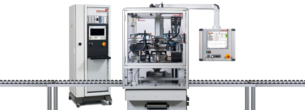
GLP3-M
Electric motor testingTest benches for functional and safety testing of all types of engines.
- asynchronous motors
- synchronous motors
- stepper motors
- BLDC
- DC motors …
- engine attachments
- brake
- temperature sensor
- additonal heating
- fan
- encoder, resover, multiturn encoder
- interfaces for automation such as PROFINET, EtherCAT, TCP/IP …
- interfaces to various ERP and MES systems …
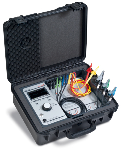
MotorAnalyzer2 R2
The expert level tester for your motor serviceCheck your motor’s health!
- asynchronous, synchronous and direct current machines, brakes, transformers, coils …
- repair, service, maintenance, servicing
- ALL-IN-ONE – 15 test methods in one device
- surge voltage test up to 3 kV !
- high voltage DC and insulation up to 6 kV
- resistance, inductance, impedance, capacitance, RIC test
- troubleshooting and fault location
- adjusting the neutral zone on DC motors
- light and portable
- battery or mains operation
- PC software for printing and saving
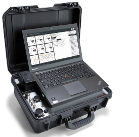
Dynamic MotorAnalyzer
Check your motor's health!Troubleshooting & online condition monitoring of running motors/generators.
What is the cause of the problem?
The Dynamic MotorAnalyzer supports troubleshooting and analysis.
- suitable for mains and frequency inverter operation
- electrical mains and motor input data
- energy consumption, capacity utilisation, efficiency …
- mechanical power and torque …
- unique multifunctional oscilloscope
- data recorder for long-term measurements
- data recorder for real-time measurement data and playback for later analysis
- trend analysis for predictive maintenance
GLP1-g
PE conductor, insulation, high voltage and function testing deviceThe smallest safety tester in the world!
- PE/GB-resistance testers
- insulation resistance testers – IR
- high voltage testers AC/DC
- safety & function testers
- 50+ device configurations – combining up to 9 test methods in one device
- PLe, SIL3, Kat4 safety circuit (depending on device variant and degree of risk)
- table-top unit or 19″ rack mounting
- ½ 19″ or 19″ format


