Partial discharge testing has become an integral part of everyday testing.
The rapidly increasing spread of modern electric motors with frequency converters makes partial discharge testing indispensable – because it is the only way to reliably assess the suitability of your motors for frequency converter operation and to detect critical insulation weaknesses.
With the increasing importance of partial discharge testing we hear two questions more and more often – which we are happy to answer:
- How exactly does a partial discharge test actually work?
- And what technological advances have been made in this field?
What is partial discharge or a partial discharge test anyway?
A full discharge is an electrical breakdown, often visible and audible – similar to lightning. In contrast, a partial discharge is only a very weak partial breakdown in one part of the winding insulation. Over time, this partial breakdown, also known as partial discharge, leads to ever-increasing insulation damage, which in the worst case can extend to a total loss. This is exactly what must be avoided. The partial discharge test serves this purpose. It helps you to recognize in advance the total failures that may occur in the future.
Partial discharge test according to IEC 61934 and DIN EN 60034-18-41
The partial discharge test is used to check the winding quality of winding materials. It can be performed in conjunction with the high-voltage test (sinusoidal) as well as with the surge test. The main purpose of this test is to detect quality defects in windings which cannot be detected with the conventional high-voltage test or the surge test alone.
The measurement technology in combination with high-frequency filter technology makes the system extremely resistant to interference. Therefore the system is ideally suited for use in the field or in production.
The partial discharge measurement (filtering and analysis) is fully integrated in the MTC2/MTC3. Only the decoupling (measurement) of the actual partial discharge signal takes place outside the test device. This is necessary to measure as close as possible to the winding and to adapt optimally to the respective measurement situation. The test on an open stator winding is realized with a highly sensitive measuring antenna or on a completely mounted motor with a special coupler. Both the antenna and the special coupler can optionally be connected to the MTC2/MTC3. Thus you are optimally equipped for any measurement task.
The further development of the antenna makes the measuring system even more sensitive than ever before. Any partial discharge that occurs is clearly visible and has a sufficient signal-to-noise ratio.
KEY-FACTS
- determination of the inrush and intermittent voltage according to IEC 61934
- very high reproducibility thanks to special filter technology
- special coupling technique for measuring fully assembled motors
- extremely resistant to interference due to special, high-frequency filter technology
- shielding of the testing area not mandatory – but optional
- partial discharge test up to 25 kV
- qualification of enamelled copper wires (twisted pair), enamel insulation and impregnation process
- testing for frequency converter suitability
Partial discharge test on an open stator winding
The partial discharge measurement at an open stator winding is performed via a highly sensitive measuring antenna which is put inside the test object or placed close to the test object.

Partial discharge test at a completely assembled motor
The measuring at a completely assembled motor cannot be performed via an antenna, as the high-frequency signals are shielded by the closed motor cabinet. In these cases the measuring performed via a special coupler which is attached to the measurung lead.

Partial discharge using the surge voltage
The test is performed either manually or fully automatically. In manual mode, the operator increases the voltage continuously while monitoring the partial discharge signal.
Automatic operation enables the analysis of all three phases fully automatically via a test sequence. The following values are determined per phase:
- PDIV (Partial Discharge Inception Voltage)
- PDEV (Partial Discharge Extinction Voltage)
- RPDIV (Repetitive Partial Discharge Inception Voltage)
- RPDEV (Repetitive Partial Discharge Extinction Voltage)
In this case it is also not necessary to run the full ramp. If it is necessary to quickly differentiate between “GO” and “NO GO” in production, it can be operated with a preset test voltage.

The following diagram shows the beginning of the surge voltage oscillation (yellow) and the partial discharge pulses (red).

Partial discharge test at HV-AC
The test is performed automatically via a test sequence set beforehand. A ramp function is applied, in which the test voltage is continuously increased. As soon as the first partial discharges occur, this voltage is stored as PDIV
(inception voltage).
Next, the voltage is reduced until the partial discharge disappears. This point is identified as PDEV (extinction voltage) and also stored. Due to preferably short test times in production the partial discharge’s intensity can also be determined at a preset voltage. Thus it can be quickly distinguished between “GO” and “NO GO”.
In addition it is also possible to perform the test manually. Here the operator continuously increases the voltage while monitoring the partial discharge signal.

The VoltageAnalyzer – measuring accuracy at its best
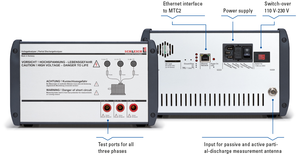
The VoltageAnalyzer serves for measuring surge-voltage signals directly at the winding of the motor. The frequency response covers a range from DC up to very high pulse frequencies in the MHz-range. This makes the VoltageAnalyzer the ideal tool for high-precision surge-voltage and partial discharge measurements.
With the VoltageAnalyzer, voltages and voltage peaks can be measured right where they occur, e.g. in the motor terminal board or right at the winding connections.
Voltage measurement for surge voltage and partial discharge
It may happen that the voltage measured in the surge tester does not exactly match the voltage at the DUT. This is caused by the fact that the unavoidable lead inductances and capacitances between the test leads can change the voltage curve of the surge signal on its way to the DUT. This effect becomes more intense the steeper the surge pulse rises.
In order to accurately measure the partial discharge inception voltage actually applied to the motor terminal board during a partial discharge test, for example, it is necessary to measure directly at the terminal board using the VoltageAnalyzer.
KEY-FACTS
- accurate surge measurement directly at the winding or at the motor terminal board
- active test probe with integrated switch-over between three phases
- potential-free voltage measurement
- influences of the measuring line on the signal path are eliminated
- accurate measurement of partial-discharge voltages – PDIV, RPDIV, PDEV, RPDEV
- perfect for standard-compliant measurement according to DIN EN 60034-18-41:2014
- detection and logging of pulse rise times
Partial discharge test on an open stator winding
For testing three-phase motors or stators quickly and without re-clamping, the VoltageAnalyzer has three test ports. These are connected directly to terminals U, V and W of the test object via the shortest possible test leads. The test-point switch-over between the three test connections in the VoltageAnalyzer is fully automatic and synchronous to the surge test.

The SCHLEICH advantage!

Surge impulse measured by the VoltageAnalyzer
- measured directly at the motor terminals
- precise overshoot measurement
- exact peak and peak to peak voltage measurement

Surge impulse measured without VoltageAnalyzer
- signal waveform is not measured at the motor terminals
- high damping of the overshoot signal
Connection configuration of the VoltageAnalyzer to MTC2/MTC3 and DUT


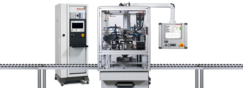
MTC2
Surge tester with 6, 12, 15, 25, 30, 40 or 50 kVThe state of the art winding tester.
- surge test plus standard-compliant partial discharge measurement
- resistance
- insulation resistance
- high voltage DC plus polarization index / DAR
- high voltage AC
ideal for service, production, automation, quality control, laboratory, R&D …

MTC3
Winding tester fully automatic for automation, laboratory ...Reliable winding testing for production, research and quality.
▪ standard motors
▪ special motors
▪ automotive drives
▪ transformers
▪ coils …
▪ ALL-IN-1 with over 20 test methods
▪ in-line partial discharge testing
▪ interfaces for automation such as PROFINET, EtherCAT, TCP/IP …
▪ interfaces to ERP, MES and CAQ systems …

VoltageAnalyzer
Intelligent probe up to 6 kVPrecision measurement of the surge test directly at the winding.
- consideration of the influence of the measuring leads
- super fast sampling rate
- high measuring resolution
- plus simultaneous PD measurement with passive or active antenna
- integrated switchover between the test leads