Know How
Voltage Check
With the voltage check it is checked whether the voltage has actually been connected reliably during the high-voltage test.
Voltage check via minimum current
![]()

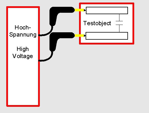
At the high-voltage test it is really important to check whether the voltage is acutally connected correctly to the test object. Here there are several possibilities. The simplest possibility is the setting of a minimum current. This minimum current always has to flow during the test. Thus the test current is in a preset window: the minimum current has to be exceeded – the release current must not be exceeded.
The minimum current is often formed “inherently” as the test object is capacitive. This is for example always the case at motors, test objects with shielded capacitors and test objects with long leads. In the capacity a reloading current is continuously flowing during the test, which is evaluated as minimum current. In case the current does not flow the test does not have any voltage.
If the test object is less capacitive only a low minimum current is formed (clearly lower than 1mA). In this case you can often use a trick by connecting an additional resistance as charge to the test object. This resistance makes sure that an evaluable mimimum current flows again.
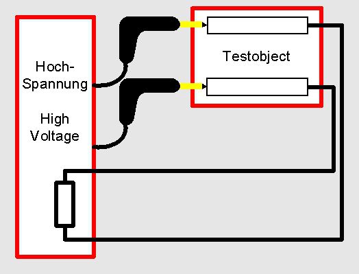
Voltage check via minimum current with high-voltage resistance
At a test with DC-high-voltage a minimum current set is only possible in a restricted way. At a DC-test with a capacitive test object there is only a charging current when connecting the voltage. Nevertheless the tester can also measure this with the corresponding settings.
![]()


The picture shows an application example for the voltage check via the minimum current at a drilling machine with plastic housing. All screws are to be tested regarding isolation towards the mains leads. For this a pole of the test voltage from the high-voltage device is connected to the mains connection. The other pole is connected to the screw that is to be tested at first. Via another connection (thus the screw is connected 2-times) this screw is connected to the next one. At the last screw a final resistance is connected. The thing for this is that the voltage is picked on at one point of the head of the screw and picked off again at another contact point (isolated from the first pick-on point). Thus a connection up to the final resistance is generated via the heads of the screws. Only when the connections are connected correctly a minimum current can flow in the final resistance. In an automatic test process it can be tested with this method whether all screws are connected to the voltage.
Voltage check via four-wire-technique
Another alternative is the voltage check via four-wire-technique. With this technique the test object is connected to the voltage at 2 points and the voltage is picked off at to other points. The picked-off voltage is lead back to the tester and measure there.
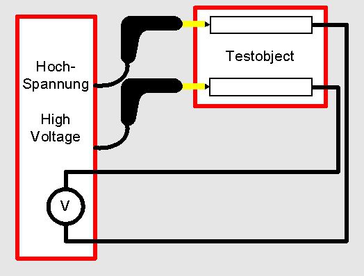
Voltage check with return
![]()

The four-wire-technique makes sure that the high-voltage is connected to the test object in the correct level during the test.
A typical application is for example the high-voltage test between 2 lead paths. The high-voltage is fed in at the beginning of the lead paths and picked off at the end of the lead paths again. Then it is returned to the tester for the evaluation.