Know How
Four-Wire-Technology
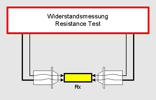
The picture shows a resistance Rx and 2 test probes. The test probes have 2 contact tips each which are insulated against each other. Thus there are totally 4 connection points at the resistance to be measured.
At the four-wire-technology (also called Kelvin test) the transition resistance of the contact point between the test tip and the test object is compensated. This is done by touching the test object through the contact tip with two separated contacts.
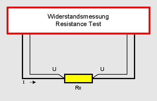
In this process one contact serves to feed the test object with current and the second contact serves for tapping the voltage drop at the test object. As the contact resistance is still “after” the tapping of the voltage drop it is not important for the measurement of the voltage drop anymore. The provision for the measurement of the voltage drop is a high-ohmic voltage tester. By means of this the contact resistance at the second contact point is completely insignificant compared to the resistance of the voltage tester, expressed in percent.
This method is always used when very low resistances are measured. This is especially valid for the PE test or the measurement of low-ohmic winding resistances.
In case it is maybe possible only with a great expenditure to perform the contacting of the test object in a four-wire technique it makes nevertheless sense to perform the inlet lead up to the test object in four wire technique. Thus the test result does not depend on the lead length of the test cords and on indefinable transition resistances at the tester (like for example relay).
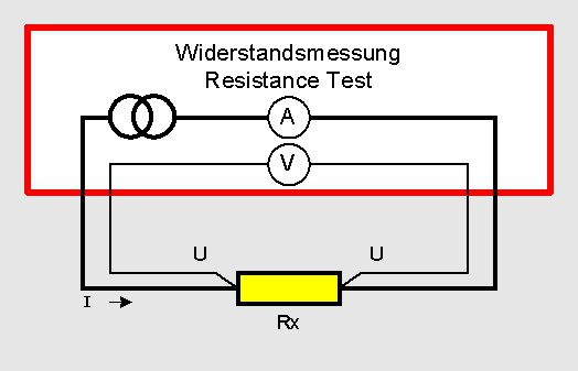
The picture shows the wiring diagram of the single resistances of the equivalent circuit. The resistances 1 and 4 are the resistances at the contacting point of the current connections. The resistances 2 and 3 are the contact resistances in the voltage measuring circuit. You clearly see that the resistances 1 and 4 are irrelevant at the voltage drop measurement at the resistance Rx . As already written above the internal resistance of the voltage tester has to be quite high in relation to the resistances 2 and 3 so that there are no measuring errors. This is the case in practice as 2 and 3 are mostly below 1 Ohm. The internal resistance of the voltage tester is normally > 1MOhm.
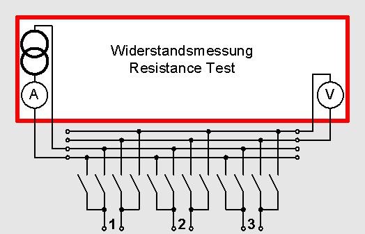
Four-wire-matrix for the resistance measurement
To connect the test object in four-wire measurement SCHLEICH offers different clamps.
-
Kelvin-clamps in different sizes
-
4-wire-test tips
The four-wire-measurement can also be used at testers with a relay matrix. In this case 4 relays per connection point at the test object are required. Thus it is possible that each connection point can be measured against each other connection point. At this method the corresponding current relay and the voltage relay (sense) always switch at the same time. This means that for 4 relays at one connection point only 2 outputs are required at the tester.