
Inspecting and adjusting encoders
Check and adjust all types of electric motor encoders with the SCHLEICH-EncoderAnalyzer.
And it’s as easy as that: Connect the encoder to the EncoderAnalyzer directly or via a connection box and enter the technical data of the encoder.
The EncoderAnalyzer supplies the encoder with the necessary voltage, checks the current consumption and measures all signals.
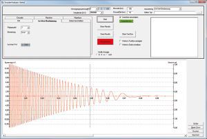
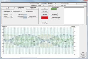
On the PC screen, the EncoderAnalyzer shows you a clear analysis and possible encoder errors. In addition, you receive a meaningful graphical representation of all encoder signals, just like an oscilloscope.
For the adjustment of resolvers and Hall sensors, the EncoderAnalyzer also measures the EMF (BEMF) of the motor in order to provide you with the best possible support for angle adjustment of the encoder.
The EncoderAnalyzer is the optimal single device for repair and production.
The EncoderAnalyzer can also be integrated directly into SCHLEICH motor test benches.
Please note that the EncoderAnalyzer is offered exclusively for integration into a motor test station. It is not possible to purchase a stand-alone device.

|
|||
|
|||
|
|
|||
|
|||
|
|
|||
|
|||
|
|||
|
|||
Modern drives are often equipped with rotary encoders. For the operator, a detailed inspection is made difficult due to the large diversity of encoders in the market. This applies in particular for repairers of electric motors but also for analyses in production. An extensive inspection without special measuring technology is not possible.
The EncoderAnalyzer offers valuable services by simplifying the encoder inspection as it supplies the encoder with voltage and measures all signals. Afterwards they are automatically evaluated. The result is indicated either as a clear GO (o.k. ) or a clear NOGO (not o.k.).
The following rotary encoders and sensor systems may be inspected:
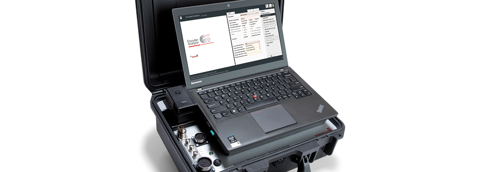
The EncoderAnalyzer consists of two components: The measuring module and the analysing software, which is to be installed on a PC.
The measuring module provides a connection for the encoders to be inspected. Furthermore, additional components for supplementary measuring functions may be connected to the measuring module.
The measuring module performs the tests. For this, it determines millions of measuring values during one revolution and transfers them to a PC. The communication between measuring module and PC is done by a Gigabit-Ethernet connection. By means of the analyzing software the measured results are automatically evaluated. At the end of an inspection the software presents the result on the screen. For a better understanding, errors detected at a broken rotary encoder, are graphically displayed like in an oscilloscope.
The test results are stored in a database. If requested, a detailed test report may be printed.
The rotary encoder to be inspected is connected with the measuring module by a measuring lead. On the measuring module´s front side up to 2 measuring sockets are available for the connection of the measuring leads. verbunden. The number of measuring sockets depends on the ordered options. The EncoderAnalyzer with all 12 measuring channels is equipped with 2 measuring sockets.
A voltage supply of 3…30 V is also integrated in the EncoderAnalyzer. Depending on the encoder, voltage level and maximum permissible power consumption are entered by the operator via software input. During the measurement the EncoderAnalyzer monitors the power consumption. In case the maximum permissible value is exceeded, the voltage supply is automatically switched off.
The fast and intelligent measuring technology and the user-friendly, intuitive analysis software are perfectly matched with each other. Only a few settings and selections are sufficient, to configure the measurement for the encoder to be tested.
The extensive evaluations lead to clear and easy-understandable results. Special or detailed knowhow is not necessary while dealing with the analysis software. The software helps and supports during the connection and evaluation of encoders.
As supplement to the encoder analysis the software also assists during the angle adjustment of rotary encoders. No matter, if the rotary encoder needs to be adjusted by mechanical turning or if only the angle offset needs to be determined, the software graphically supports the operator during the adjustment. Depending on the encoder type and the EncoderAnalyzer´s equipment, the offset angle may also be written in the rotary encoder.
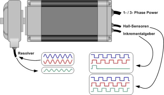
EMF-measurment Resolver signal
1. Rotary encoder- / Resolver test
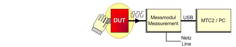
The rotary encoder is connected with the measuring module with an appropriate connection lead. Afterwards you manually turn the encoder´s axis. The arising impulses are digitized and evaluated by the measuring module.
2. Rotary encoder- / Resolver test together with the motor
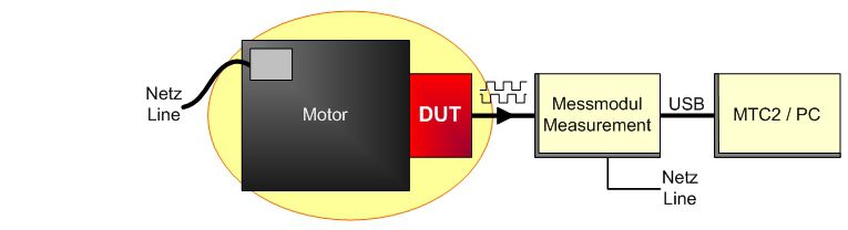
The rotary encoder mounted on the motor is connected with the measuring module with an appropriate connection lead. Afterwards the motor is directly operated from the mains or via a frequency converter. The arising impulses are digitized and evaluated by the measuring module.
3. Rotary encoder- / Resolver test by means of a test installation
In a special SCHLEICH-test installation the rotary encoder is mechanically coupled with a small drive motor. Via an appropriate connection lead it is connected with the measuring module. For testing purposes the module actuates the drive motor. The arising impulses are digitized and evaluated by the measuring module. Depending on the encoder to be tested the motor´s angle position may also be determined.
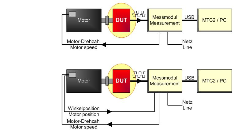
4. Resolver- / Hall element adjustment
For the adjustment the resolver, which is still connected with the motor, is additionally connected with the measuring module via an appropriate connection lead. Furthermore the motor is mechanically coupled by a drive motor. Afterwards the drive motor is directly operated from the mains or, better, by a frequency converter. The arising pulses and the Back-EMF induced in the windings are digitized and evaluated by the measuring module. The measuring module derives the adjustment-information from the measured values which is also indicated on the screen.
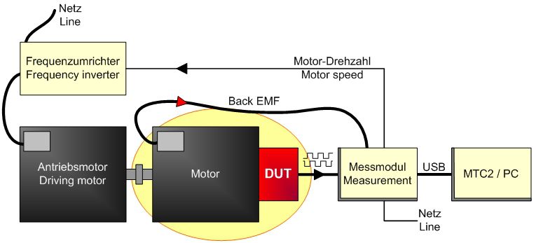
For testing purposes, the encoder has to be supplied with DC-voltage which is generated in the measuring module and in the requested voltage level. The supply voltage is shortcircuit proof and the encoder´s power consumption is also inspected. In case the power consumption is too high, the measuring module automatically switches-off the supply voltage due to safety reasons.
The software is equipped with a database with storage capacity for thousands of encoders and resolver.
For the inspection of an encoder, the corresponding data has to be contained in the database. The data consists of relevant information as e.g. the encoder type, the supply voltage level, the pin assignment and so on. Based on this information, the software assists you regarding the suitable connection cable and how to properly connect the encoder.
Furthermore the database contains even more information. Although they are not important for the measurements, they inform about further details of the encoder.
General information
Encoder
Resolver
Single- and Multiturn encoders
EMF-Measurement
⇒ More details available under Downloads.
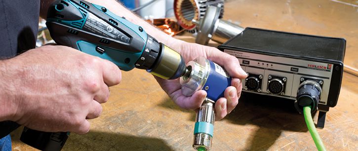
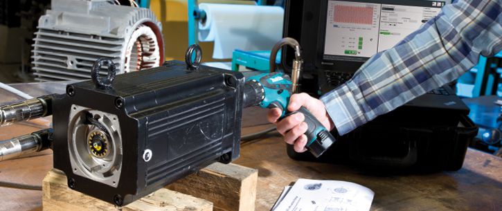
The EncoderAnalyzer is only able to inspect encoders with rotating shaft. For this, the encoder may be directly driven by the motor at which the encoder is installed.
But also in case the encoder is to be inspected separately, it has to be driven by constant speed. For this, as example, a cordless screwdriver can be used.
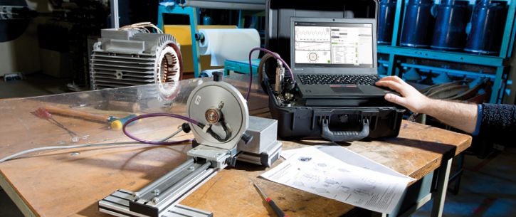
As an alternative, the encoder/ resolver may also be inspected separately on a small test stand. The test stand is equipped with a small motor which drives the encoder with selectable speed. The EncoderAnalyzer collects all signals and determines all parameters. In case target values are entered in the EncoderAnalyzer, an automatic target-actual comparison is done by the software, followed by an evaluation.
Für weitergehende Informationen steht Ihnen unser technischer Vertrieb auch gerne telefonisch zur Verfügung.