Dynamic MotorAnalyzer

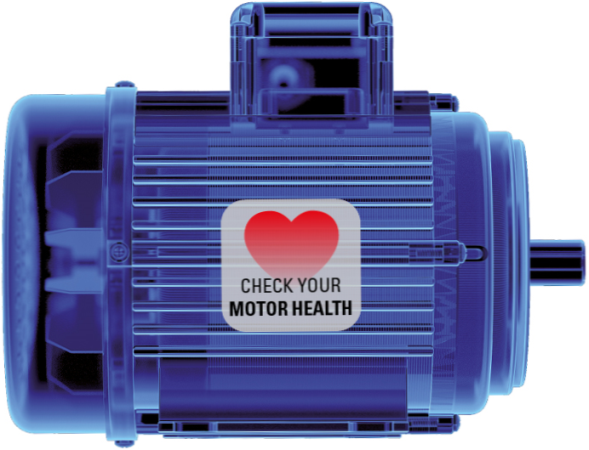
Check your motor's health!

Dynamic motor analysis allows you to check your running motor in its working environment. The Dynamic MotorAnalyzer measures the electrical parameters and can calculate mechanical parameters from these measurements.

With the Dynamic MotorAnalyzer you can check the mains supply, internal conditions and load conditions of your motor. An analysis of the entire electric motor is performed based only on the 6 electrical measured values (3 x U, 3 x I).

As a supplement to the MotorAnalyzer1, MotorAnalyzer2 R2 and the MTC2 winding testers, the Dynamic MotorAnalyzer completes your test device portfolio.

Key-Facts

All in One – Motor analysis.

  • Power Quality Analysis
  • Motor Quality Analysis
  • Motor Load Analysis
  • Professional motor analysis without special knowledge required from the operator
  • Perfect for trouble shooting at the mains or frequency converters
  • Perfect for trouble shooting at electric motors
  • Perfect for trouble shooting at the mechanical load
  • Perfect for preventive maintenance
  • Determination of mechanical power parameters and torque
  • Trend analysis, Forecast
  • Long-term analysis
  • Motor start-up analysis
  • Efficiency analysis
  • Capacity-analysis
  • Energy costs analysis
  • Continous real time long-term measurements, measured values are constantly displayed
  • Direct voltage measurement up to 700 Veff
  • Indirect voltage measurement via PTs up to 50 kV
  • Current clamp measuring ranges from 5 – 5.000 Aeff
  • Current measurement via CTs up to 10 KAeff
  • Integrated oscilloscope function to assess voltages, currents and powers…
  • Switch-over to country-specific units as e.g. Nm, lb-ft, HP, KW and other
  • Data base to store test results
  • Extensive, self-configurable printing report
  • Battery-operation
  • Worldwide voltage supply 90 – 250 V / 47 – 63 Hz


Beschreibung

Professional motor analysis – no technical expertise required.

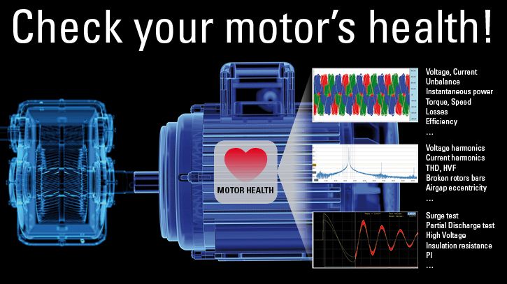
The dynamic motor analysis allows the inspection of a running motor in its working environment. For this,  the electrical parameters of mains supply and motor are measured and, among others, the corresponding mechanical parameters are calculated. The aim is to receive an analysis of the electric motor, its mains supply and its load conditions  – only based on 6 electrical measured values ( 3x voltage and 3x current).

The Dynamic MotorAnalyzer significantly simplifies the motor inspection- without requiring special knowledge or skills from the operator. It is the perfect supplement to our SCHLEICH- winding testers MotorAnalyzer2 and MTC2.


Dynamic motor analysis in practice.

It often occurs that motors are operated under overload conditions or fail due to unknown reasons.  This may be due to the mains supply, the motor itself or its load.  The error may result from electrical or mechanical reasons.

It is often hard to detect the error cause as motors are often part of a complex plant or as it is installed in plants with difficult access.
In most cases the motor lead in the motor´s control cabinet is easier to access. Here is the perfect place to measure the 6 electrical values (3x U and 3x I).  By means of a variety of analyzing methods the Dynamic MotorAnalyzer evaluates the motor´s condition. It is also possible to speak about the motor´s „health condition“.

This makes the Dynamic MotorAnalyzer an easy-to-use measuring tool for detecting complex problems within the machine´s system.  Basically it is always better to determine the origin error cause before repairing or exchanging the motor. In case the problems are not properly detected the electric motor is likely to fail again. This would cause even more downtime- and repair costs, which should be avoided in any case.


Typical measurements with the Dynamic MotorAnalyzer

The Dynamic MotorAnalyzer not only supports you in finding typical erros, but also in finding those ones which are rather difficult to detect and then to solve the problem afterwards. For this, it uses the latest methods and technologies regarding MCSA (MCSA – Motor Current Signature Analysis).
Some examples for typical errors:

  • voltage fluctuations
  • overtones/ harmonics
  • rotor bar problems
  • Mechanical overload
  • Frequency converter problems


Periodic controls.

Motor failures and associated machine down times may be reduced by preventive maintenance.   For this, inspections of electric motors are carried out in regular intervals. The Dynamic Motoranalyzer stores all test results, evaluates them and presents them as trend analysis.  Based on the graphical and easily understandable trend development you can easily find out, if a motor´s condition is getting worse and avoid downtimes by purposeful maintenance.

A perfect supplement to the Dynamic MotorAnalyzer´s test results is the ombination with the test results of the electric motor testers MotorAnalyzer2 or surge voltage tester MTC2. The test results from the motor testers may be saved together with the Dynamic MotorAnalyzer´s  test results  in one data base and jointly evaluated for the trend analysis. Based on the combination of test methods, you receive an even deeper look in your electric motor´s condition or technical installations.

Your production´s availability and efficiency may be increased, as downtimes can cause costs of more than hundreds of thousands Euros per hour!
Thus, the aim of preventive maintenance is to avoid interruptions and unplanned downtimes.


Technik

All benefits at a glance.

  • Power Quality Analysis
    • Voltage per phase
      • Fundamental oscillation and collective oscillation
      • Phase-to-neutral -voltages -U1N – U2N – U3N : Uinstantaneous, Umin – Uaverage – Umax
      • Phase conductor voltages-U12 – U23 – U31Uinstantaneous, Umin – Uaverage – Umax
      • Harmonics, up to the 50th harmonic
      • THD – Total harmonic distortion
      • HVF – Power reduction factor according to NEMA  (National Electrical Manufacturers Association)
      • CF – Crest factor
    • Unbalance between the 3 phases
    • Deviation to Unom
    • NEMA Derating, American Association: National Electrical Manufacturers Association
    • Frequency, min. – average – max.
    • Phase angle between the 3 phases
  • Motor Quality Analysis
    • Current per phase
      • Fundamental oscillation and collective oscillation
      • Motor current I1 – I2 – I3 : Iinstantaneous, Imin – Imittel – Imax
      • Harmonics, up to the 50th harmonic
      • THD – Total harmonic distortion
      • CF – Crest factor
    • Unbalance between the 3 phases
    • Current harmonics
    • Current´s frequency range
  • Motor Load Analysis
    • Power measurement as:
      • 1-Wattmeter-method
      • 2-Wattmeter-method (Aron circuit) with conversion to 3-Wattmeter-method
      • 3-Wattmeter-method
    • Power per phase
      • P – Active power
      • S – Apparent power
      • Q – Reactive power
    • Unbalance between the 3 phases
    • Overall power
      • P – Active power, Pinstantaneous, Pmin – Paverage – Pmax
      • S – Apparent power, Sinstantaneous, Smin – Saverage– Smax
      • Q – Reactive power, Qinstantaneous, Qmin – Qaverage– Qmax
    • Power harmonics
    • Power´s frequency range
    • cos φ, power factor PF
    • Speed determination
      • For this, an additional tachometer with laser sampling has to be ordered
      • For this, also a DC-tachometer may be connected
      • The speed is recorded even during long-time measurements
      • Speed may also be entered manually
      • Automatic speed determination from the motor´s current at asynchronous motors
      • Speed measurement at motor shaft
    • Torque
    • Minimum value
      • maximum value
      • minimum value
      • Line recorder to display the torque´s temporary course/ torque monitoring
      • torque range
      • torque ripple
    • efficiency
  • Measuring inputs U + I
    • 3 x 24 bit forU
    • 3 x 24 bit for I
    • Measuring rate 100 Ks
  • plus free measuring inputs
    • 6 x 12 bit for arbitrary signals
      • e.g. tacho speed
      • e.g. flow
      • e.g. pressure
      • e.g. vibration
      • e.g temperature
      • and more
  •  Voltage measuring range
    • Direct measurenent up to 700 Veff between outer conductors
    • Indirect measurment via PTs up to 50 kV
  • Current measuring range
    • from 5 – 3.000 A
    • Current measurement via CTs up to 10 kA
  • Weight 3 kg
  • Operating temperature 5 – 50° C
  • Battery-operation
  • Worldwide voltage supply 110 – 250 V / 47 – 63 Hz


Further facts.

  • Voltage displayed analog/digital
  • Current displayed analog/digital
  • Direct 3-phase voltage measurement or via voltage transformers
  • 3-phasige current measurement via current clamps, Rogowski clamps or current transformers
  • Phase sequence indication in polar coordinates (U&I)
  • Real time oscilloscope for mains analysis
    • rms values – sine wave illustration (perfect for FU-analysis)
    • U1N , U2N , U3N
    • U12 , U23 , U31
    • U1N – U2N – U3N -unbalance
    • U12 – U23 – U31 -unbalance
    • I1 , I2 , I3
    • I1 , I2 , I -unbalance
    • trigger for numerous events
    • falling or rising trigger
    • pre-trigger
    • graphical oscillation as periodical illustration
    • RMS-values (RMS) as from a line recorder
    • Zoom function
    • 2 x measuring markers to measure times and intervals
    • 2 x measuring markers to measure voltages and voltage differences
    • Unbalance-power reduction factor according to NEMA (National Electrical Manufacturers Association)
  • Real time oscilloscope for motor analysis
    • rms values – sine wave illustration (perfect for FU-analysis)
    • U1N , U2N , U3N
    • U12 , U23 , U31
    • U1N – U2N – U3N -unbalance
    • U12 – U23 – U31 -unbalance
    • I1 , I2 , I3
    • I1 , I2 , I -unbalance
    • P1 , P2 , P3, Ptotal
    • trigger for numerous events
    • falling or rising trigger
    • pre-trigger
    • graphical oscillation as periodical illustration
    • RMS-values (RMS) as from a line recorder
    • Zoom function
    • 2 x measuring markers to measure times and intervals
    • 2 x measuring markers to measure voltages and voltage differences
    • Unbalance-power reduction factor according to NEMA (National Electrical Manufacturers Association)
  • Symmetrical components
  • FFT up to 25 KHz
    • linear, logarithmic or dB display
  • Start-up transients
    • triggering for a selectable phase
    • trigger for numerous events
    • falling or rising trigger
    • pre-trigger, to also see the measured values before the event (look at „historical values“)
  • start-up process
    • triggering for a selectable phase
    • falling or rising trigger
    • pre-trigger
  • Long-term recording
    • triggering for a selectable phase, voltage or current
    • triggering for one of the free measuring channels
    • falling or rising trigger
    • pre-trigger
  • Phase-sequence correction possible, in case operator has created an incorrect connection
  • 3-phasige current measurement via current clamps, Rogowski coils or current transformers
    • current clamps with measuring range switchover


⇒ Find more details under Downloads.

  • SCHLEICH GmbH
  • An der Schleuse 11
  • 58675 Hemer | Germany
  • +49 (0) 23 72-94 98-0
  • +49 (0) 23 72-94 98-99
  • info(at)schleich.com