Test Method
Partial discharge at surge voltage
The partial discharge test is used to check the quality of winding goods. The test can be carried out in connection with the high-voltage test (sinus) as well as with the surge voltage test. The objective is to detect quality defects in windings which cannot be detected with the conventional high-voltage test or the surge test alone.
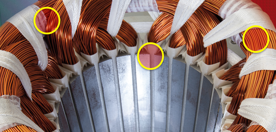
The PD test identifies insulation weaknesses at the points marked in yellow.
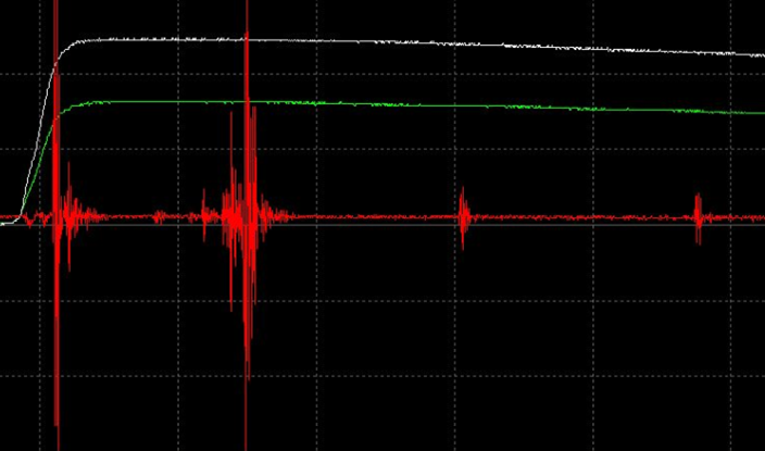
For example, this is what a PD signal looks like.
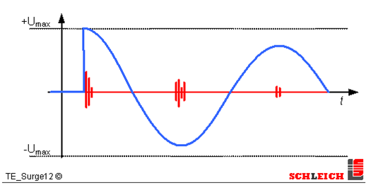
PD occurs at these locations when surge voltage is applied.
The coupling technology in combination with high-frequency filter technology makes the system extremely resistant to interference. It is therefore ideally suited for use directly in the field or in production.
Partial discharge measurement (filtering and analysis) is fully integrated into the test instrument. Only the decoupling (measurement) of the actual partial discharge signal happens outside the device. It is necessary to do so in order to best suit the specific measurement environment. Testing an open stator winding or a fully assembled motor is not a problem for the test instrument.
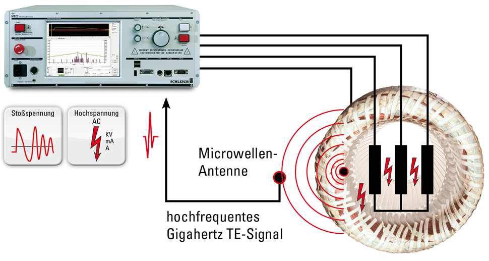
Partial discharge measurement on an open stator winding is done by means of a highly sensitive measuring antenna which is placed in the DUT or in its close vicinity.
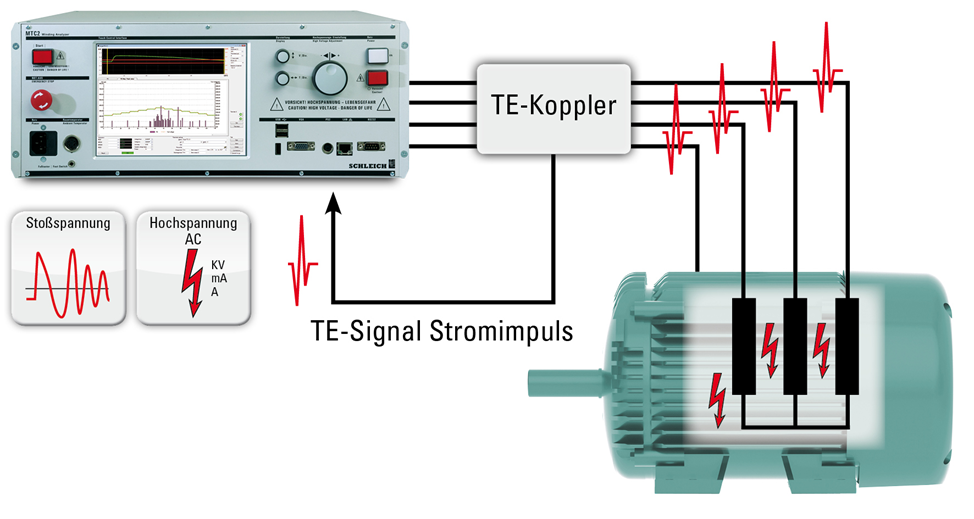
Measurements on a fully assembled motor cannot be taken using an antenna, as the high-frequency signals are shielded by the sealed motor frame. In this case measurements are taken with a dedicated coupler, which is looped through the test lead.
Both the antenna and the dedicated coupler can be optionally connected to the MTC2. That way, you are well equipped for any measurement task.
The combination of these two test methods for partial discharge testing in a single device is unparalleled anywhere else in the industry.
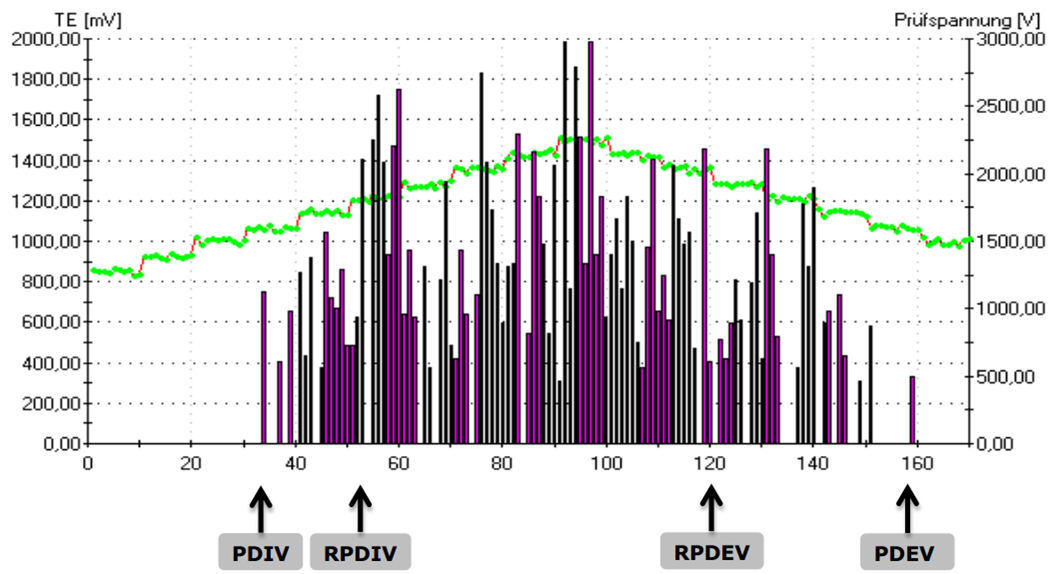
Standard-compliant fully automatic evaluation and documentation in accordance with DIN IEC/TS 61934
Automatic operation permits fully automated testing of all three phases via a test sequence. The following values are determined for each phase: PDIV ( inception voltage), PDEV ( extinction voltage), RPDIV (repetitive inception voltage) and RPDEV (repetitive extinction voltage). Testing is done either manually or fully automatically. In manual mode, the operator gradually increases the voltage while monitoring the partial discharge signal.
Here again, it is not necessary to use the entire ramp of the test. If a quick distinction between OK and NOK has to be made in production, a fixed test voltage can be used.
All results are automatically saved and documented.
Which products does SCHLEICH offer?
- assessment of single windings, winding systems and insulation systems
- assessment of enamelled copper wires (twisted pair), enamel insulation, impregnation processes
- combination test equipment (combination with other tests such as resistance, high voltage etc.)
- manual tests
- fully automatic tests
- very high reproducibility due to specialized filter technology
- partial discharge tests up to 25 kV
- no shielding of the test area needed
- test equipment of different instrument classes