Test Method
Insulation Resistance

The insulation resistance test can be performed at devices of protection class I as well as protection class II. It is checked, whether the ohmic insulation resistance exceeds the limit value stipulated in the standards. The test is to detect, whether too high leakage currents could occur in the test object.
If the insulation resistance is too low (and if there is also a PE error), a too high touch voltage could occur at the metallic parts of the device. If these metallic parts were touched, the so-called touch current could run through the person to ground.
Especially at devices of protection class II, insulation faults at metallic parts can be very dangerous, because a discharge of the current via the PE is not possible.
The measuring of the insulation resistance is performed by connecting a 500 Volt DC test voltage to the current-conducting leads against ground. In this process the current-conducting leads are often connected to each other. In this case the total resistance of all insulation resistors switched in parallel is detected during the test.
Since the test is performed with direct voltage, the insulation capacities do not influence the test. Only the ohmic insulation resistances are detected.
If the insulation capacities are quite high, the insulation-resistance test must be take longer, so that the insulation capacities can be charged at the beginning of the test. This can possibly take some 1/10 seconds, because at the insulation resistance-test the test current is limited to max. 3mA.
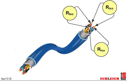
Insulation resistance tests are often performed at various test points by contacting the test points manually with high-voltage test pistols.
It is also possible to build fully-automatic testers with extensive matrixes (switch-over fields) for the automatic testing at several HV test points. There is almost no limitation for the amount of matrix points.
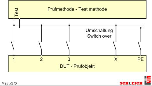
Easy switchover to test from different test points against a central test point, e.g. for testing PE.
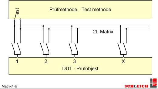
2-wire matrix, to test any test points “anyone against anyone”.
The insulation resistance test takes place with complex theoretical view at a replacing display, consisting of 4 basic components.
These are:
- C = capacitor between both poles
- Rs = surface resistance
- Rpi+Cpi = equivalent of the polarization index
- Riso = insulation resistance
Why?
The test object has an insulation resistance between two test points. This is the resistance Riso. This resistance is usually quite high and is between some 100MΩ up to 10TΩ.
In addition the test object also has a capacity between both test points. This is either formed between the windings to be tested or from the windings to the body. Between the windings it is usually lower than from the winding to the body. Capacities occur between uninsulated metal surfaces. The bigger the surface or the lesser the distance of the metal surfaces towards each other the bigger is the capacity. With in the stator the windings form one metal surface and the sheet packets the other. The bigger the stator (size) the bigger become the surfaces and thus the capacity.
An electric product often has bare uninsulated electrical leads. This is for example valid for a DC motor. At the surface of the leads electrically conducting dust may be deposited and/or humidity condensed. This results in a kind of surface resistance. In the ideal case this should be unlimited but sometimes it can become extremely low (< 1MΩ).
Electrical insulating material like for example resin and so on have dipole similar molecules. Thus they show a +/- polarization. When connecting a high-voltage DC all molecules adjust to the electrical field. Only after the end of a time this polarization is finished. this should be simulated by the RC element.
Which currents arise from this?
After having connected the test voltage a total current (Iges) arises which consists of 4 single currents.
Total current = Iges = Ic + Is + Ipi + Iiso
Via the ohmic law the total insulation resistance is calculated.
This is: Rgiso = Uhv/Iges
Due to the fact that both currents Ic and Ipi become zero after a time this time has to be waited for for a detailed evaluation of the insulation resistance.
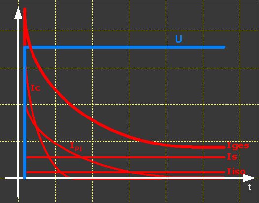
The charging of the capacitor is done fast and finished after a few seconds in most of the cases. This aim is to charge the capacitor within max. 30 seconds. After this time ic is 0:
The charging of the polarization capacity takes considerably more time. In the worst case this could take up to 10 minutes at an electric motor. Among such conditions it thus could take more than 10 minutes until the real insulation can be detected.
Which testers does SCHLEICH supply?
- single testers
- combination testers (combination with safety tests)
- Different versions in the range of 10 TΩ
- Manual tests via test probes
- fully automatic tests
- matrixes with up to 500 clamps and fully-automatic switchover
- various tester classes
Standard committees
For legal reasons, in many cases, we cannot make an obligatory statement about the test conditions. Important for the application is the currently valid standard for your product to be tested.


Depending on the geographical location of the product, the standards to be applied can vary. For further information, please refer to the following institutes.
![]()
![]()
![]()
![]()
![]()