Know How
Squirrel Cage
 |
|
| MTC2 | SQUIRREL CAGE | |
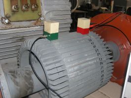
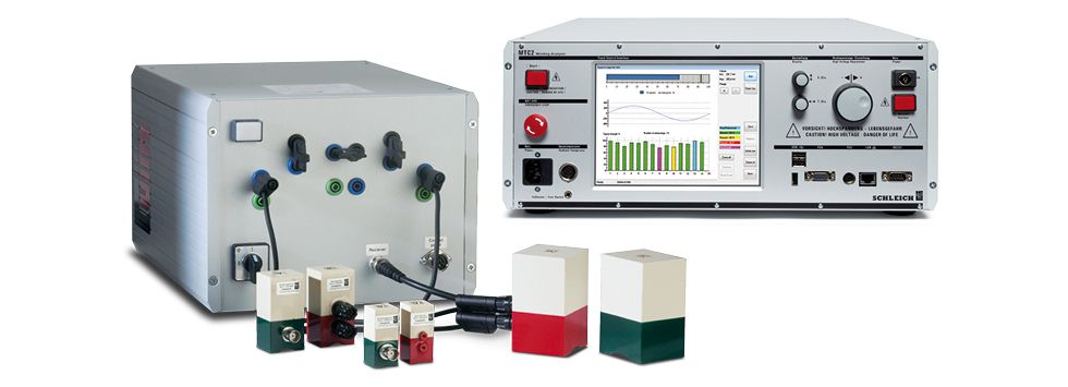
Ideal test procedure for checking and locating faults at squirrel-cage motors, armatures, stators and capacitors. The test procedure operates in combination with the surge voltage tester MTC2. For this an extension unit is connected to the MTC2.
| Functioning |
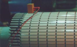
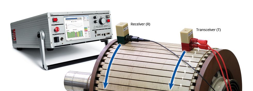
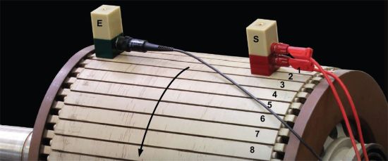
Two test probes are used for the test. They are to be connected to the outside of the test object above the slots. The first probe (T) transmits a signal to the test object; the second probe (R) receives the signal. The receipt signal is measured in the MTC2 and the signal strength is displayed on the screen.
Please number the individual slots in advance. At the subsequent measuring please position the probes above the individual slots at the opposite edges of the test object in a way that the maximum signal strength in the MTC2 is displayed. The MTC2-software supports you in an optimum way. After finding the optimum probe position you can store the signal in the MTC2 with the corresponding slot number. Please perform this measuring at each slot one after another. The MTC2 collects and stores the measuring values at each slot until all slots are measured.
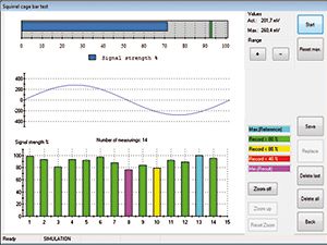
Already during the measuring the MTC2 compares the available measuring values and detects any irregularities of the resistances within the slots. The measuring values of the slots to each other should be almost the same. If the differences are too high there is a fault. Based on your numbering you can immediately locate the defect space and repair it if necessary.
 |
|
| MTC2 | ROTOR-KURZSCHLUSSSCHLÄUFER-STATOR-TEST | |
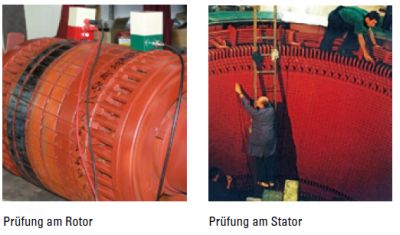
Optimum test process for testing and locating defects at short-circuit armatures, armatures, stators, alternators. This test process works in connection with the surge voltage tester MTC2 of SCHLEICH or as stand-alone.
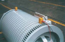
Two test probes are used for testing. They have to be installed at the outsides of the test object via the slots. The test is performed one after another at each slot. Due to the automatic comparison of the single slot test values among each other irregularities of the resistances within the slots are detected.
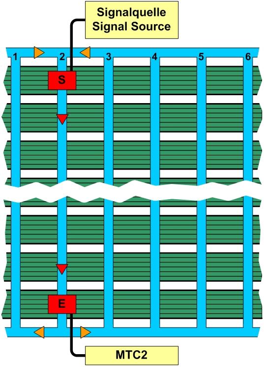
Two test probes are used for the test. The first probe (S) sends a signal to the test object, the second probe (E) receives this signal. The MTC2 measures the receipt signal and the signal strength is shown on the screen.
Before the start of the measurement it makes sense to mark the slots with a figure beginning with one. This can be done without any problems with a colored pen.

For the test you can position the probes on each slot at the opposing outer edges of the test object so that a maximum signal strength is shown in the MTC2. The MTC2 software supports you in this process. After you found the best probe position you can save the signal with the corresponding slot number in the MTC2.
You perform this measurement at each slot one after another. Thus the MTC2 collects and saves the measuring values at each slot until all slots are measured.
In case a fault occurred during the test this is no problem. You can delete the last measurement without any problems or select an individual test of a certain slot and delete it. Afterwards you can perform the test at the deleted slot again.
The MTC2 compares the available measuring values already during the test. The measuring values per slot should preferably be equal. If the differences are too big there is a fault. As you have marked the slots with figures before you can locate the faulty position immediately and repair it, if necessary.
 |
|
| MEASURING PRINCIPLE | |
The measuring principle refers to the induction of a special voltage via the transmit probe (S) in the test object (for example a squirrel-cage motor). This voltage lets a current flow that is measured by the receipt probe (E). When comparing the currents at the end of the measurement all slots should be equal at a proper armature.
| EXTENT OF DELIVERY | |
| 4023215 | signal source in a transport box |
| 4023216 | transmit probe up to 4…10mm slot distance |
| 4023217 | transmit probe up to 8…20mm slot distance |
| 4023218 | transmit probe up to 16…40mm slot distance |
| 4023224 | transmit probe up to 30…60mm slot distance |
| 4023219 | receipt probe up to 4…10mm slot distance |
| 4023220 | receipt probe up to 8…20mm slot distance |
| 4023221 | receipt probe up to16…40mm slot distance |
| 4023223 | receipt probe up to 30…60mm slot distance |
| 4023214 | software module within theMTC3 |
| 4023222 | stand alone software module for a laptop or PC |
| RECOMMENDED TEXT BOOK OF DR. NEVEN SRB | They can be purchased via SCHLEICH. | |
| The Winding Technology at Electric Motors | Service at Electric Motors | ||||||||||||||||||||||||||||||||||||
|
|
|
||||||||||||||||||||||||||||||||||||
The author Neven Srb is exclusive technology partner of SCHLEICH GmbH.
|
|||||||||||||||||||||||||||||||||||||