Know How
Relay Matrix
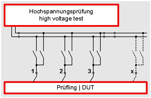
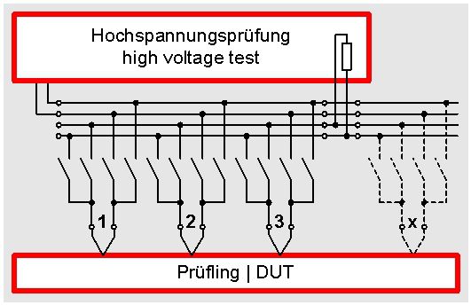
The picture shows the basic principle of a relay matrix at the high-voltage test. Both poles of the high-voltage tester are connected to a kind of bus. 2 relays per test point are connected to this bus. The tester can trigger each relay individually on the matrix. Thus it is possible that at each connecting point either the first or the second pole of the high-voltage is connected.
The operator prepares a test program for testing. This test program consist of single steps, which run individually one after another during the test. In the test program it is stipulated per test step which pole of the high-voltage tester is to be connected to which connection point Thus a random test combination of the individual connection points among each other is possible. Thus in a way “each against each” can be tested. Of course it is also possible that it is tested at the same time not only between 2 connection points. In one test step a random number of connection points can be tested at the same time.
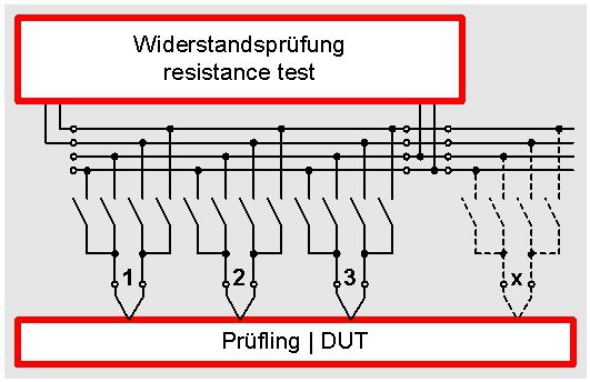
| 4-wire matrix for the resistance test |
Of course it is also possible to design the matrix for the  four-wire-test. For this two additional relaiys (i.e. totally four) are necessary per connection point. Thus the expenditure is twice as high because not only the test lead but also the sense-lead has to be connected. The following picture shows the matrix with 4-wire test at the example of a resistance test. The advantage of this technology is that the power, the relay and the other transition resistances are automatically compensated. Thus you always receive a perfect resistance test.

| 4-wire matrix for the high-voltage test |
The 4-wire test can also be used at the high-voltage test. The advantage is that the high-voltage that is connected to the test object can be lead back to the tester. Thus a voltage check is performed. Only in case the voltage that is lead back from the test object can be measured correctly the voltage is really connected to the test object. In automatic test processes this shows the necessary process safety.

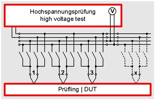
Instead of a measurement of the voltage that is lead back to the tester the lead back voltage can also be charged with a high-voltage resistant terminating resistance. When functioning correctly a corresponding current flows through the terminating resistance. This can be evaluated as minimum current. Thus this minimum current can be evaluated as voltage check at SCHLEICH testers.