Know How
RC element
In a simple and theoretical view the insulation resistance takes place at one RC-element. The RC-element is the idealized form of the ratio at the test object.
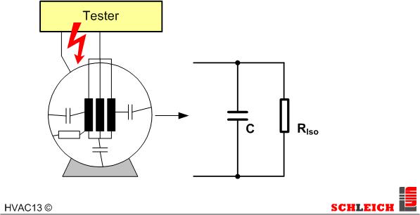
Why? The test object has an insulation resistance between both test points. This is the resistance Riso. This resistance is often quite high and has a value of some 100Mohm and higher. In addition the test object also has a capacity between both test points. This capacity is either formed between the windings to be tested or from the winding to the body. Between the windings it is normally lower that from the winding to the body. Capacities occur between insulated metal surfaces. The bigger the surface and the smaller the distance of the metal surfaces towards each other the bigger is the capacity. In a stator the windings form one metal surface and the sheet packages the other. Thus the bigger the stator (the size) the bigger are the surfaces and thus the capacity.
In case the high-voltage test is performed with AC a high capacitive reload current flows within the stator (RC-element). This capacitive reloead current is often clearly higher than the leakage current through the ohmic resistance Riso (which is very high-ohmic). This means that the reload current flowing continuously through the capacitor (due to AC) overlapses the actually to be tested error current through the resistance. The capactive reload current is no error current but a current caused by physical law which always exists. It is not really a quality characteristic of the stator. Of course the current must not be too high but it is not a reliable statement regarding the quality of the insulation.
Advantage of the HV-DC test
The reload current can be avoided by means of the high-voltage test with DC. Only during the increase of the test voltage up to the final value a charging current (Ic) is flowing within the capacitor. When the voltage does not change anymore the current only flows within the ohmic insulation resistance (Iiso).
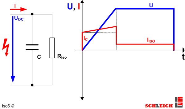
A constant charging current flows when then voltage is constantly increased in form of a ramp. During the “charging phase” there is also the current through the insulation resistance. This increases proportionally to the increase of the voltage. At the end this leakage current remains as insulation current. Thus an informative insulation resistance test is only possible after the end of the charging phase of the capacitor.